CyberOne EC DX IOM Manual
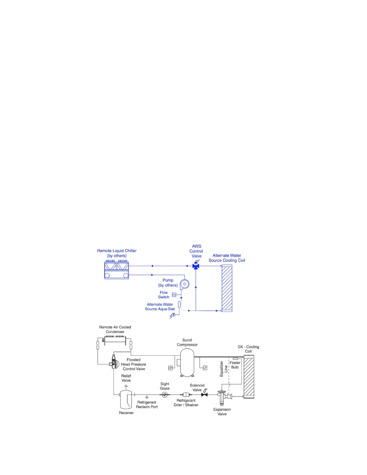
1.6 Free-cooling Operation
The free-cooling configuration is available to minimize the
use of compressor operation during low ambient conditions
for system energy savings. An FC (free-cooling) system
uses a remote drycooler or cooling tower to provide
water/glycol coolant to a free-cooling coil positioned
within a DX refrigerant system. If outdoor air
temperatures permit free-cooling operation (adjustable
user set point), the free-cooling mode is enabled to take
advantage of the low ambient conditions to provide cooling
with partial use or without the use of the system
compressor(s). Free-cooling provides an excellent
opportunity for reduced operational cost by reducing the
compressor operating hours.
The free-cooling sequence is enabled when the entering
fluid temperature falls below the user adjustable free-cooling
enable set point and the return air temperature rises to the
free-cooling set point plus dead band. The drycooler pump
activates and the 3-way control valve directs chilled water/
glycol coolant to the FC coil. The outdoor fluid cooler is
controlled by first switching the leaving fluid control set
point from typical DX heat rejection to free-cooling control
(adjustable set point, ambient air) and by controlling the
leaving fluid to its user adjustable set point. The free-cooling
control valve opens proportionally to the demand for cooling
based on the return air temperature’s deviation from set point.
If the return air temperature continues to rise, the free-cooling
valve position eventually reaches 100% open, maximizing
the flow of coolant through the free-cooling coil. Continued
operation in this position indicates the A/C unit is unable
to lower the air temperature to the desired set point in the
free-cooling mode.
The compressor activates if the DX cooling stage enable
temperature set point has been reached or if the control valve
position reaches 100% open for 20 seconds (default). The
free-cooling circuit and the compressor operate in parallel to
provide maximum cooling. The 3-way control valve continually
modulates the flow of coolant in response to temperature with
the compressor running.
The compressor cycles off based on the normal compressor
temperature cut-out settings once the set point is maintained.
As the outside air temperature increases above the ambient
air switch-over setting, the fluid cooler controls cycle back to
typical DX heat rejection allowing the leaving fluid control set
point to increase above the prevailing ambient conditions. The
indoor unit’s inlet fluid temperature sensor monitors the fluid
temperature and deactivates the free-cooling mode once the
fluid temperature increases above the user adjustable enable
set point. The system compressors become the primary
cooling source and will activate as the return air temperature
increases above the set point.
Figure 3. Free Cooling Diagram
6
 Loading...