EasyManua.ls Logo

Sub-Zero 642/F

Sub-Zero 642/F
134 pages
To Next Page IconTo Next Page
To Previous Page IconTo Previous Page
Loading...
Icemaker Information
600 Series
(Prior to #1810000)
6-3
#3756270 - Revision B - January, 2006
Holding Switch
Cover
Support Plate
Timing Gear
Drive Motor
Thermostat
Support
Shut-off Switch
Ice Ejector
Bearing / Inlet
Ice Mold and Mold Heater
Ice Stripper
Lever Arm
Water Valve Solenoid Switch
(Location of Thermal-Mastic)
Timing Cam
Ice Level Arm
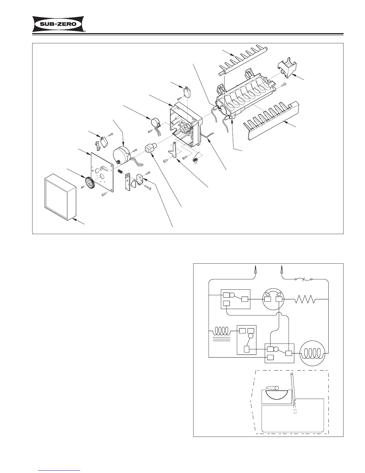
Figure 6-1. Diagram of Icemaker Components
ICEMAKER OPERATION
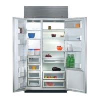
The following series of electrical schematics illustrate a
typical icemaker cycle of operation. Below each
schematic is a diagram indicating the approximate loca-
tion of the ice ejector and ice level arm during the
phase the schematic indicates.
Freeze Phase of Ice Making Cycle (See Figure 6-2)
The ice mold is filled with water.
The thermostat is open.
No icemaker components are energized.
Figure 6-2. The Freeze Phase
APPROXIMATE POSITION
OF ICE EJECTOR AND
ICE LEVEL ARM
DURING OPERATION
115 VOLTS
60 CYCLES
SHUT-OFF SWITCH
THERMOSTAT
MOLD HEATER
WATER
SOLENOID
SOLENOID SWITCH
MOTOR
HOLDING SWITCH
NO
NC
C
NC
NC
NO
NO
C
C
TCO
ICE MOLD
ICE BUCKET
WATER

Table of Contents

Related product manuals