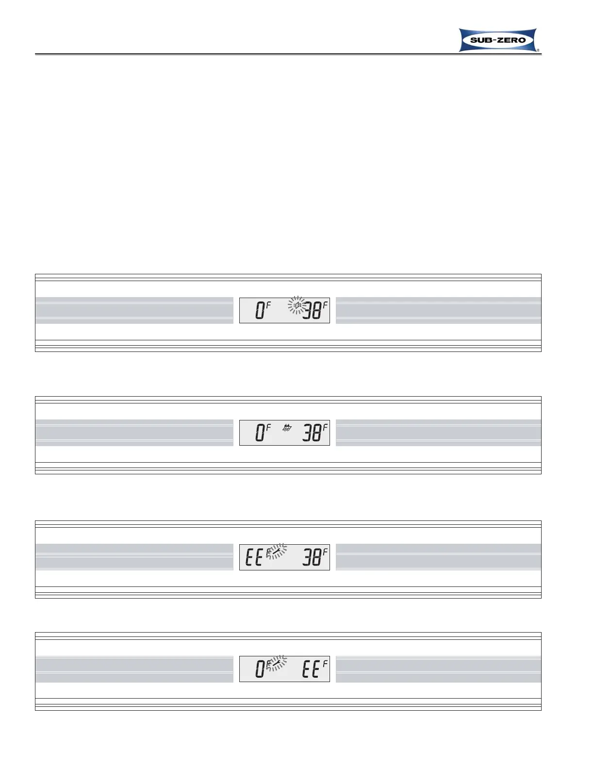
Figure 3-52. Pure Air Icon Flashing = Air Purifier Components need to be Replaced.
After Replacing Filter Cartridge, Press PURE AIR Key for 5 Seconds to Reset Timer
Figure 3-53. Water Filter Icon Appears = Water Filter need to be Replaced.
After Replacing Filter, Press Filter Reset Button behind the Unit Grille for 5 Seconds to Reset Counters
POSSIBLE INSTRUCTION AND ERROR/FAULT INDICATORS
The diagrams on these pages illustrate what a customer may see in the LCD if the appliance needs attention.
NOTES:
• To clear instruction indicators (See Figures 3-52 & 3-53) and restart the appropriate timer, the instructions must be
followed, then press the appropriate key or reset button as described.
• For thermistor faults described below (See Figures 3-54 & 3-55): Thermistors can be tested by submersing them
in a glass of ice water (~32°F / 0°C) for approximately five (5) minutes, then checking for 30,000 to 33,000 ohms.
• To clear fault indicators and Fault Codes (See Figures 3-54 to 3-59) the problem must be corrected, then press
the ALARM key for fifteen (15) seconds (See Figure 3-60). Failure to clear Fault Codes will result in the highest
priority fault indicator reappearing in the LCD when the unit is switched back ON.
• If a customer needs to suspend a Major Fault Code for twenty-four (24) hours, while waiting for a Service
Technician, they could press and hold ALARM then POWER keys simultaneously for less than 5 seconds. Doing
this, as apposed to clearing the Fault Cold as described above, would maintain all Fault Code history data for the
Service Technician.
 Loading...