#824974 - Revision C - November, 2016
3-20
Component Removal
M Series Wall Oven
M Series Wall Oven
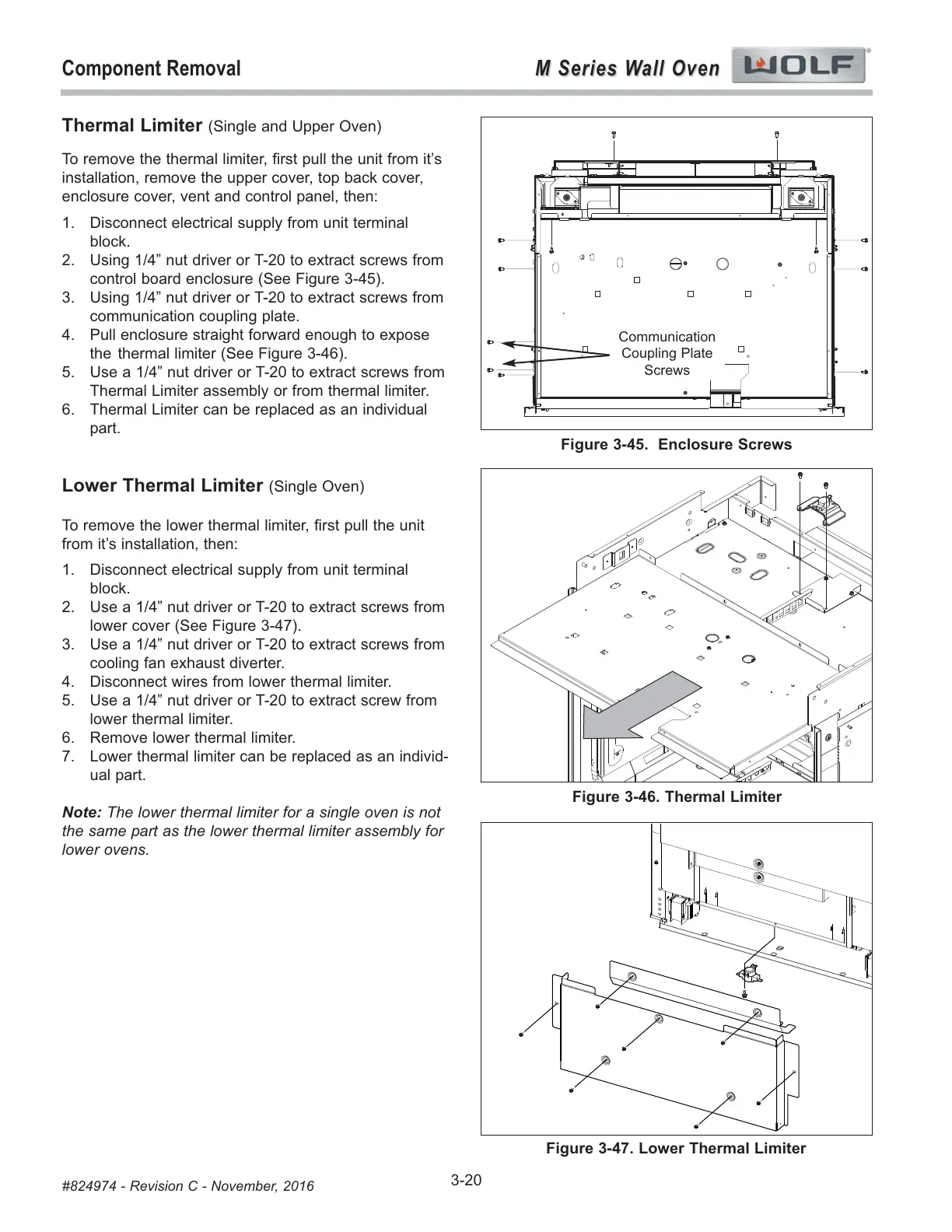
Thermal Limiter (Single and Upper Oven)
To remove the thermal limiter, first pull the unit from it’s
installation, remove the upper cover, top back cover,
enclosure cover, vent and control panel, then:
1. Disconnect electrical supply from unit terminal
block.
2. Using 1/4” nut driver or T-20 to extract screws from
control board enclosure (See Figure 3-45).
3. Using 1/4” nut driver or T-20 to extract screws from
communication coupling plate.
4. Pull enclosure straight forward enough to expose
the thermal limiter (See Figure 3-46).
5. Use a 1/4” nut driver or T-20 to extract screws from
Thermal Limiter assembly or from thermal limiter.
6. Thermal Limiter can be replaced as an individual
part.
Lower Thermal Limiter (Single Oven)
To remove the lower thermal limiter, first pull the unit
from it’s installation, then:
1. Disconnect electrical supply from unit terminal
block.
2. Use a 1/4” nut driver or T-20 to extract screws from
lower cover (See Figure 3-47).
3. Use a 1/4” nut driver or T-20 to extract screws from
cooling fan exhaust diverter.
4. Disconnect wires from lower thermal limiter.
5. Use a 1/4” nut driver or T-20 to extract screw from
lower thermal limiter.
6. Remove lower thermal limiter.
7. Lower thermal limiter can be replaced as an individ-
ual part.
Note: The lower thermal limiter for a single oven is not
the same part as the lower thermal limiter assembly for
lower ovens.
Figure 3-45. Enclosure Screws
Figure 3-46. Thermal Limiter
Communication
Coupling Plate
Screws
Figure 3-47. Lower Thermal Limiter