Section 2
DESCRIPTION
8
2.5 COMPRESSOR DISCHARGE SYSTEM, FUNC-
TIONAL DESCRIPTION.
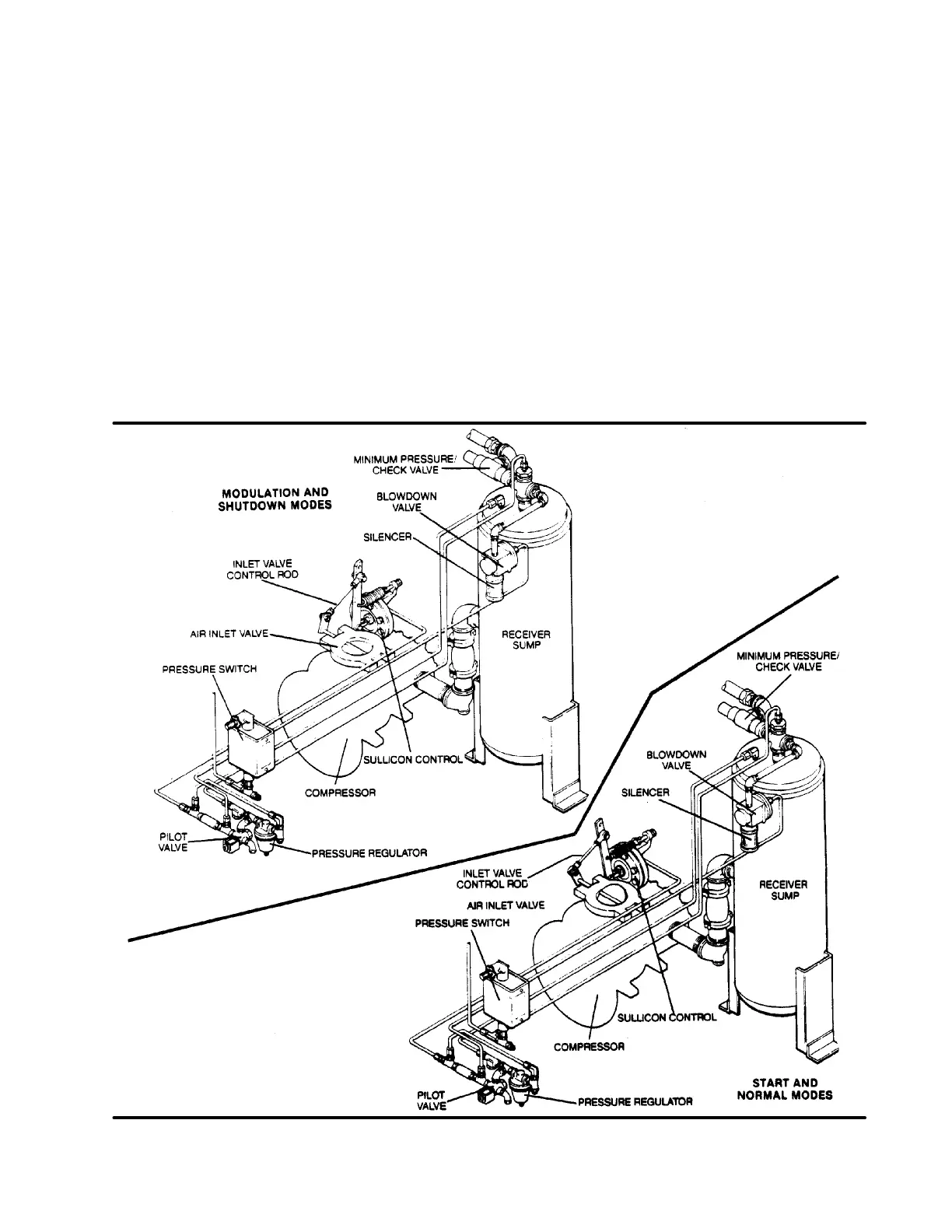
Refer to Figure 2-4. The compressor unit dis-
charges the compressed air/fluid moisture through
a discharge check valve into the combination re-
ceiver/sump. The discharge check valve prevents
air in the receiver from returning to the compression
chamber after the compressor has been shut down.
The receiver has three basic functions:
1. It acts as a primary fluid separator.
2. Serves as the compressor fluid sump.
3. Houses the final fluid separator.
The compressed air/fluid mixture enters the re-
ceiver and is directed towards the bottom of the
separator element. The direction of movement is
changed and its velocity significantly reduced, thus
causing the large droplets of fluid to fall to thebottom
of the receiver/sump. The fractional percentage of
fluid remaining in the compressed air collects on the
surface of the separator element as the com-
pressed air flows through the separator. A return
line (or scavenge tube) leads from the bottom of the
separator element tothe inlet region of thecompres-
sor unit. Fluid collectingon thebottom of thesepara-
tor is returned to the compressor by a pressure dif-
ferential between the receiver and the compressor
inlet. A visual sight glass is located on the return line
to observe this fluid flow. There is also an orifice in
this return line (protected by a strainer) to assure
proper flow. A gauge, located on the instrument
Figure 2-4 Compressor Discharge System

 Loading...


