EasyManua.ls Logo

Sullair 3709 - User Manual

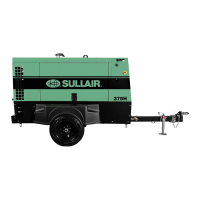
Sullair 3709
146 pages
To Next Page IconTo Next Page
Loading...
®SULLAIR®
INDUSTRIAL AIR COMPRESSOR
3000, 3000P, 3700, 4500,
3000V, 3000PV, 3700V, 4500V
30, 37 & 45 KW/40, 50 & 60HP
Air-Cooled and Water-Cooled
Standard & 24 KT
PART NUMBER:
02250155-601
KEEP FOR
FUTURE
REFERENCE
©
SULLAIR CORPORATION
The information in this document is
correct at the time of printing for utility
compressor serial number
20060701XXXX
and all subsequent serial numbers.
OPERATORS MANUAL AND PARTS LIST

Table of Contents

Other manuals for Sullair 3709

Questions and Answers:

Sullair 3709 Specifications

General IconGeneral
Model3709
TypeRotary Screw
Voltage460 V
Rated Pressure125 psi
Max Pressure125 psi
Phase3 ph

Summary

Section 1 SAFETY

1.2 PERSONAL PROTECTIVE EQUIPMENT

Guidelines for required personal protective gear.

1.3 PRESSURE RELEASE

Procedures for safe pressure release.

1.4 FIRE AND EXPLOSION

Precautions against fire and explosion hazards.

1.5 MOVING PARTS

Safety measures concerning moving machinery parts.

1.8 ELECTRICAL SHOCK

Safety procedures for electrical hazards.

Section 2 DESCRIPTION

2.4 COMPRESSOR COOLING AND LUBRICATION SYSTEM, FUNCTIONAL DESCRIPTION

Function of the cooling and lubrication systems.

2.6 CONTROL SYSTEM, FUNCTIONAL DESCRIPTION

How the control system regulates air output.

Section 3 SPECIFICATIONS

3.1 TABLE OF SPECIFICATIONS - 3000, 3000 P, 3700 AND 4500 SERIES MODELS

Physical and performance data for specific models.

3.3 COMPRESSOR SPECIFICATIONS

Detailed technical specifications of the compressor.

3.11 WIRING DIAGRAM, MFV AIR-COOLED

Electrical schematic for MFV air-cooled models.

3.13 WIRING DIAGRAM, WYE-DELTA AIR-COOLED

Electrical schematic for Wye-Delta air-cooled models.

3.15 WIRING DIAGRAM, VSD AIR-COOLED

Electrical schematic for VSD air-cooled models.

Section 4 INSTALLATION

4.1 MOUNTING OF COMPRESSOR

Procedures for properly mounting the compressor unit.

4.2 VENTILATION AND COOLING

Requirements for adequate air-cooled ventilation and cooling.

4.6 ELECTRICAL PREPARATION

Instructions for customer electrical connections.

4.7 MOTOR ROTATION DIRECTION CHECK

Crucial step to ensure correct motor rotation.

Section 6 MAINTENANCE

Section 8 PARTS LISTS

Related product manuals