E900H User Manual 2: Description
02250203-986 R03
Subject to EAR, ECCN EAR99 and related export control restrictions. 21
2.6 Compressor cooling and lubrication
system, functional description
Refer to Figure 2-4. The compressor cooling and lubrica-
tion system is designed to provide adequate lubrication
a
s well as maintain the proper operating temperature of
the compressor. In addition to the cooler and fan, the sys-
tem consists of a main filte
r and thermal valve.
Fluid is used in the system as a coolant and a lubricant.
Th
e fluid is housed in the receiver tank.
Upon start up, the fluid temperature is cool, and routing
to
the cooler is not required. The fluid first enters the ther-
mal valve and then flows on to the compressor unit,
by
passing the cooler. As the compressor continues to
operate, the temperature of the fluid rises and the ther-
mal valve element begins to shift. This forces a portion of
the
fluid to the fluid cooler. The cooler is a radiator-type
that works in conjunction with a separate motor-driven
fan. The fan blows air through the cooler removing the
heat of compression from the fluid. From the cooler, the
fluid is routed back to the thermal valve.
Before the temperature of the fluid reaches the valve set
po
int, cooled fluid is mixed with warmer fluid. When the
temperature of the fluid reaches 190°F (88°C), the ther-
mal element shifts completely cau
sing all fluid to flow to
the cooler. After the fluid passes through the thermal
valve it is then directed through the main fluid filter.
There, the fluid is filtered in preparation for injection into
the compression chamber and bearings of the compres-
sor unit. The filter has replaceable elements. After the
fluid
is properly filtered, it then flows on to the compres-
sor unit where it lubricates, seals and cools the compres-
sion chamber as well as lub
ricates the bearings and
gears.
2.7 Control system, functional
description
The purpose of the compressor control system is to regu-
late the amount of air being compressed to match the
a
mount of compressed air being used.
The capacity control system consists of a pneumatic inlet
va
lve. The functional description of the control system is
described below in four distinct phases of compressor
operation. For explanatory purposes, this description
applies to any compressor with an operating range of 150
to 165 psig (10.3 to 11.4 bar). A compressor with any
othe
r pressure range would operate in the same manner
except for the stated pressures.
Start mode—0 to 50 psig (0 to 3.4 bar)
When the compressor <START> button is depressed, the
sump pressure will quickly rise from 0 to 50 psig (0 to
3.4 bar). During this period, both of the pressure regula-
tors and the solenoid valve are closed and the pneumatic
inle
t valve is inoperative. The internal spring holds the
inlet valve fully closed to reduce motor torque for starting.
After six (6) seconds the solenoid valve will open, open-
ing the inlet valve, and the c
ompressor will run at full
rated capacity. The rising compressor air pressure is iso-
lated from the service line in this phase by the minimum
pr
essure valve set at approximately 50 psig (3.4 bar).
Full load mode—50 to 150 psig (3.4 to 10.3 bar)
When the compressed air pressure in the sump rises
above 50 psig (3.4 bar), the minimum pressure valve
op
ens, allowing compressed air to flow into the service
line. A load signal is provided through a pressure reduc-
ing regulator set at 70 psig (4.8 bar) to maintain the inlet
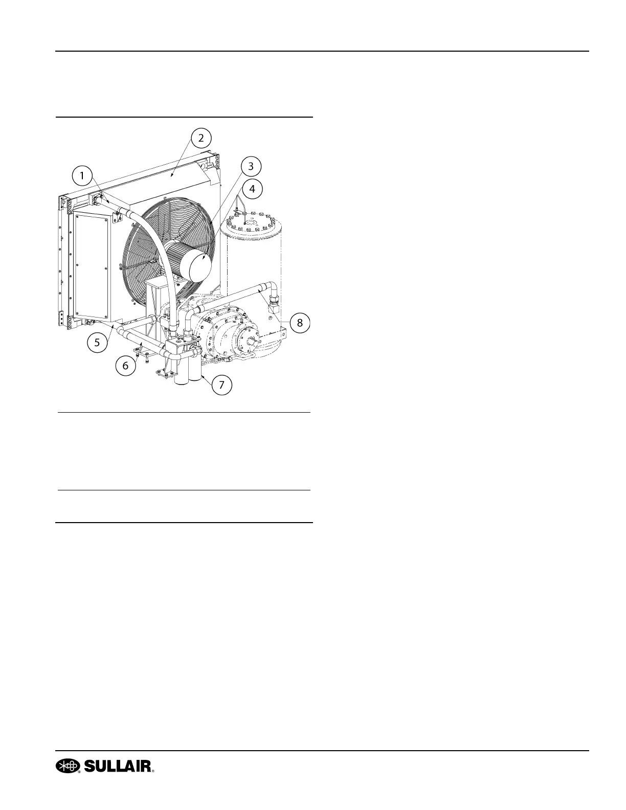
Figure 2-4: Cooling and lubrication system
1. Hose from oil cooler 5. Hose to oil cooler
2. Fan enclosure 6. Hose to unit
3. Fan guard 7. Fluid filter
4. Fan motor 8. Hose from separator
tank

 Loading...
