6
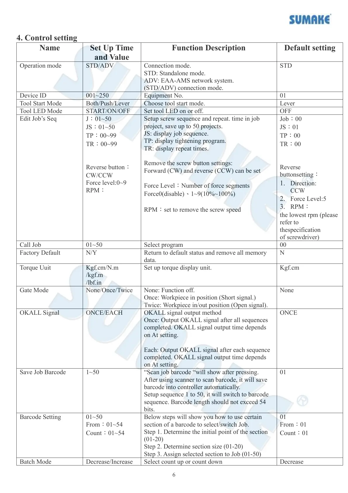
4. Control setting
Connection mode.
STD: Standalone mode.
ADV: EAA-AMS network system.
(STD/ADV) connection mode.
J:01~50
JS:01~50
TP:00~99
TR:00~99
Reverse button:
CW/CCW
Force level:0~9
RPM:
Setup screw sequence and repeat. time in job
project, save up to 50 projects.
JS: display job sequence.
TP: display tightening program.
TR: display repeat times.
Remove the screw button settings:
Forward (CW) and reverse (CCW) can be set
Force Level:Number of force segments
Force0(disable)、1~9(10%~100%)
RPM:set to remove the screw speed
Job:00
JS:01
TP:00
TR:00
Reverse
buttonsetting:
1. Direction:
CCW
2. Force Level:5
3. RPM:
the lowest rpm (please
refer to
thespecification
of screwdriver)
Return to default status and remove all memory
data.
Kgf.cm/N.m
/kgf.m
/lbf.in
Set up torque display unit.
None: Function off.
Once: Workpiece in position (Short signal.)
Twice: Workpiece in/out position (Open signal).
OKALL signal output method
Once: Output OKALL signal after all sequences
completed. OKALL signal output time depends
on At setting.
Each: Output OKALL signal after each sequence
completed. OKALL signal output time depends
on At setting.
“Scan job barcode “will show after pressing.
After using scanner to scan barcode, it will save
barcode into controller automatically.
Setup sequence 1 to 50, it will switch to barcode
sequence. Barcode length should not exceed 54
bits.
01~50
From:01~54
Count:01~54
Below steps will show you how to use certain
section of a barcode to select/switch Job.
Step 1. Determine the initial point of the section
(01-20)
Step 2. Determine section size (01-20)
Step 3. Assign selected section to Job (01-50)
Select count up or count down