10
EHYM
EHY
Series
[Y3]
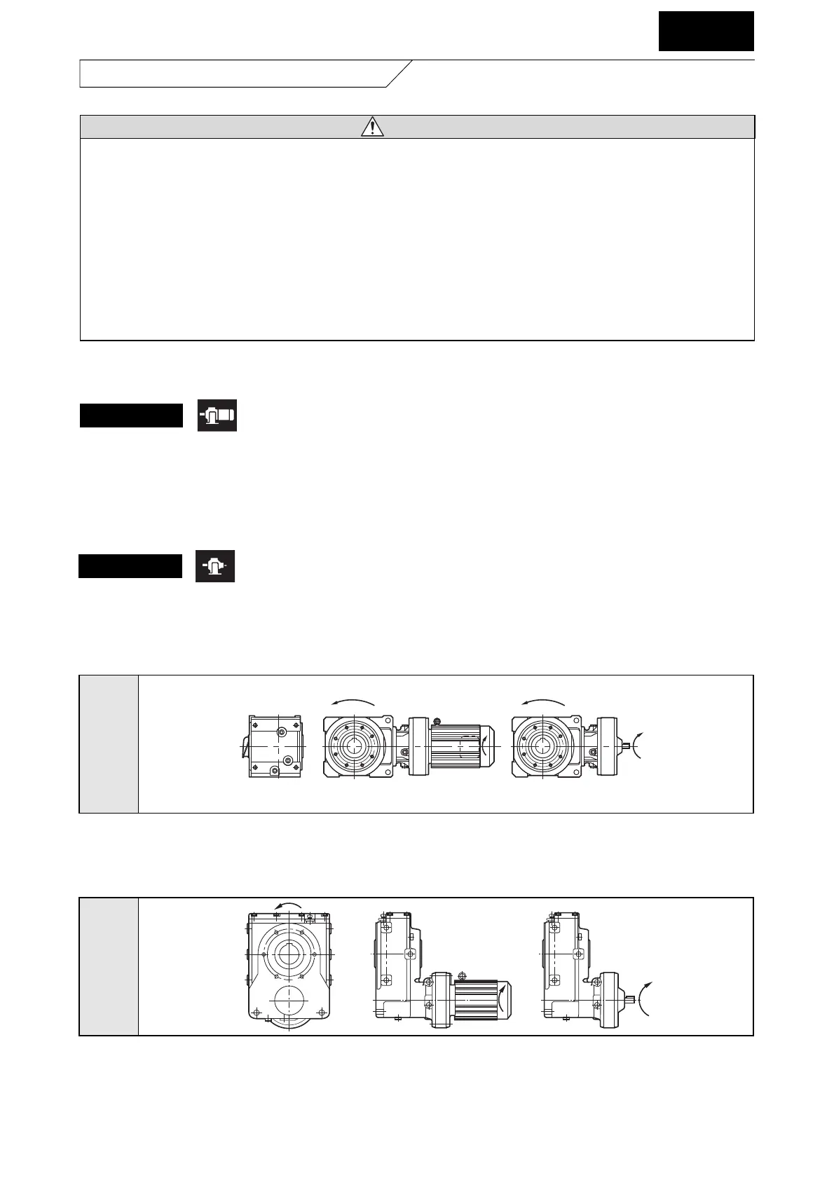
Fig. 4 Rotational Direction of Output Shaft for Helical BUDDYBOX
Relationship of rotational direction of input shaft and output shaft is as shown by the arrow in Fig. 3 and 4.
Note: • Models with reduction ratio 11 & 18 and reducers with "DA," "DB," and "DC," at the end are different from the above. Rotational direction of
output shaft is opposite from the above figure when the motor shaft and reducer type input is clockwise
• Figure above is the rotational direction for mounting style "Y1." Refer to Table 2 on page 6 or catalog for other mounting styles.
LHYM
LHY
Series
[Y1]
Fig. 3 Rotational Direction of Output Shaft for Bevel BUDDYBOX
Note: • Models with reduction ratio 11 & 18 and reducers with "DA," "DB," and "DC," at the end are different from the above. Rotational direction of
output shaft is opposite from the above figure when the motor shaft and reducer type input is clockwise
• Figure above is the rotational direction for mounting style "Y1." Refer to Table 1 on page 5 or catalog for other mounting styles.
COMMON
5. Coupling with Other Machines
CAUTION
Make sure of the rotation direction of the application machine before coupling. Difference in rotation direction may
cause injury or damage to the equipment.
Remove the temporary key on the output shaft when operating the gearmotor or reducer unit alone. Otherwise, it
may cause injury.
Place a cover to prevent touching the rotating parts. Otherwise, it may cause injury.
Be careful of the center alignment, belt tension, and parallelism of the pulleys when coupling the gearmotor or
reducer to the load. Make sure of the coupling accuracy for applications with direct connections. Adjust the belt
tension correctly for applications with belt. Make sure to tighten the bolt for pulley, and coupling before operation.
Failure to do so may result in damage of equipment or injury by broken pieces.
Gearmotor
5-1) Confirmation of direction of rotation
Fig. 3 and 4 indicates rotational direction of output shaft when wired following Fig. 25 on page 21.
• Motor shaft turns in clockwise looking from the anti-load side. This direction is as shown by the arrow in Fig. 3 and 4.
• Exchange connection R and T in Fig. 25 on page 21 with each other when rotating in the opposite direction.
Reducer

 Loading...


