5
Getting Started
Getting Started
F
EN
ES
C
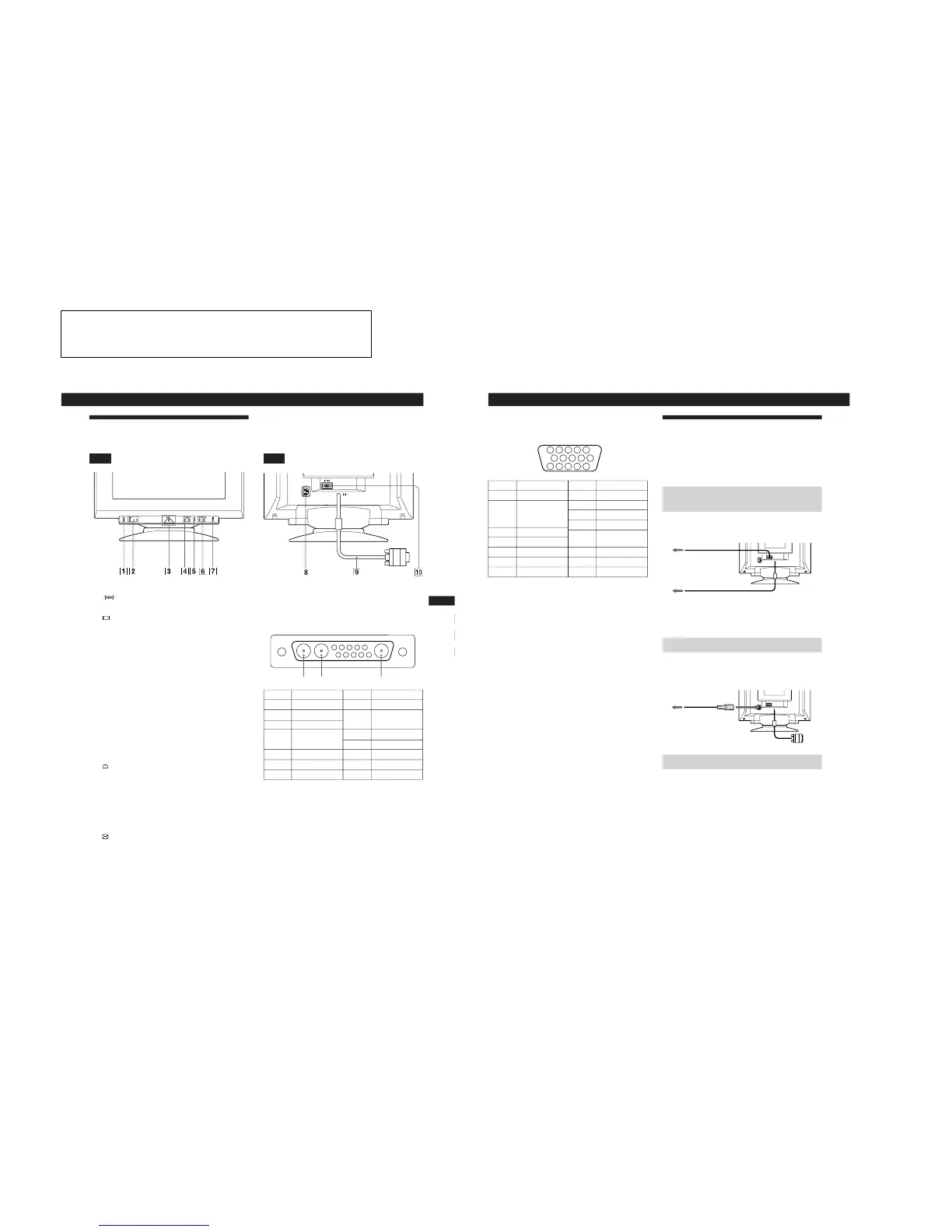
Identifying Parts and Controls
See the pages in parentheses for further details.
Front
1 (reset) button (page 16)
Resets the adjustments to the factory settings.
2 (input) button and 1 (13W3) / 2 (HD15)
indicators (pages 7 – 8)
Selects the 1 (13W3) or 2 (HD15) video input signal.
Each time you press this button, the input signal and
corresponding indicator alternate.
3 u (power) switch and indicator (pages 17,
20)
Turns the monitor on or off.
The indicator lights up in green when the monitor is
turned on, and lights up in orange when the monitor is
in power saving mode.
4 ¨ (brightness) (./>) buttons (pages 8 –
16)
Adjust the picture brightness.
Function as the (./>) buttons when adjusting other
items.
5
(menu) button (pages 7, 9 -16)
Displays the MENU OSD.
6 > (contrast) (?//) buttons (pages 8 – 16,
20)
Adjust the contrast.
Function as the (?//) buttons when adjusting other
items.
7 (auto sizing and centering) button
(page 7)
Automatically adjusts the size and centering of the
images.
Rear
8 AC IN connector
Provides AC power to the monitor.
9 Video input 1 connector (13W3 cable)
Inputs RGB video signal (0.700 Vp-p, positive).
* Pins serve a dual purpose as combined sync input and as H.sync
input if V.Sync is present on pin no. 7.
** Display Data Channel (DDC) Standard by VESA
Note
If you use a computer or video board of high output level (about 1.0
Vp-p), you may not be able to obtain the optimum display. In such
case, try decreasing the picture contrast, or use a computer or video
board with a lower output level.
(continued)
Pin No.
A1
A2
A3
1
2
3
4
Signal
C.Sync*
Bi-Directional
Data (SDA)**
V.Sync
ID (100 Ω)
ID (100 Ω)
Ground
Pin No.
5
6
7
8
9
10
Signal
Red
Green
Blue
Data Clock
(SCL)**
DDC + 5V**
––
DDC Ground**
A3
A2
A1
6
Getting Started
!º Video input 2 connector (HD15)
Inputs RGB video signals (0.700 Vp-p, positive) and
SYNC signals.
* Display Data Channel (DDC) Standard of VESA
Setup
Before using this monitor, check that the following items are
included in your carton:
• Monitor (1)
• These operating instructions (1)
Step 1: Connect the monitor to the
computer
With the computer switched off, connect the video signal
cable to the video output of the computer.
Note
Do not short the pins of the video signal cable.
Step 2: Connect the power cord
With the monitor switched off, connect one end of the
proper power cord for your local supply to the monitor and
the other end to a power outlet.
Step 3: Turn on the monitor and computer
The installation of your monitor is complete.
Note
If “OUT OF SCAN RANGE” or “NO INPUT SIGNAL” appears on
the screen, see “Warning Messages” on page 18.
to a computer with an
HD15 video output
to a computer with a
13W3 video output
to a power outlet
Power cord
to AC IN
Pin No.
1
2
3
4
5
6
7
Pin No.
8
9
10
11
12
13
14
15
Signal
Red
Green
(Composite
Sync on Green)
Blue
––
DDC Ground*
Red Ground
Green Ground
Signal
Blue Ground
DDC + 5V*
Ground
––
Bi-Directional
Data (SDA)*
H. Sync
V. Sync
Data Clock(SCL)*