Test
abort conditions
a.
engine
speed falls below 2000 rpm.
b.
current
reading is less than 5 amps.
9.
Observe final test
results. Highest
voltage
value
and peak amp reading
displayed
(Voltage
Reg-
ulator test).
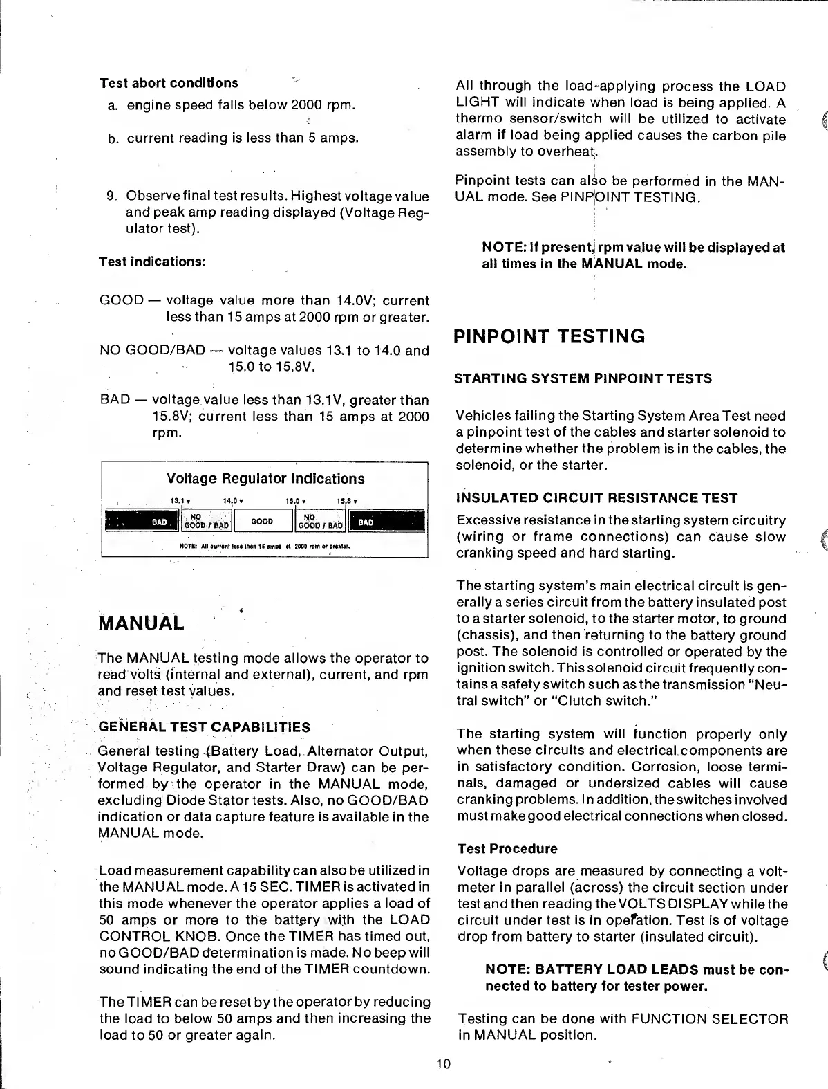
Test indications:
GOOD
—
voltage value
more than
14.0V; current
less
than 15 amps at 2000
rpm or greater.
NO GOOD/BAD
—
voltage values
13,1 to 14.0
and
15.0 to 15.8V.
BAD
—
voltage
value less than
13.1V,
greater than
15.8V;
current less than
15 amps at
2000
rpm.
v<
13
iltage R
1
v 14
egulator
0 v
15
ndicatio
0 v 15.
ns
3 v
NO
. .
GOOD /BAD
GOOD
NO
GOOD
/
BAD
BAD
|
NOTE: All current
toss
than
15 amp* at 2000
rpm or greater.
MANUAL
The
MANUAL
testing mode allows the operator to
read
volts (internal
and external), current, and rpm
and reset test values.
GENERAL
TEST
CAPABILITIES
General testing (Battery Load, Alternator
Output,
Voltage
Regulator,
and
Starter Draw)
can
be
per-
formed by the operator in the MANUAL
mode,
excluding Diode
Stator tests. Also, no GOOD/BAD
indication
or data capture feature is available
in the
MANUAL
mode.
Load measurement capability can also be
utilized
in
the MANUAL
mode.
A
15
SEC. TIMER is activated in
this
mode
whenever the operator applies a
load
of
50 amps or more to the
battpry with the
LOAD
CONTROL KNOB. Once the TIMER
has
timed out,
no
GOOD/BAD
determination is made. No
beep
will
sound indicating the end of the
TIMER countdown.
The TIMER can
be
reset
by
the
operator by reducing
the
load to below 50 amps
and
then increasing
the
load
to 50 or greater
again.
All through
the load-applying
process
the
LOAD
LIGHT
will indicate
when load
is
being
applied. A
thermo
sensor/switch will
be utilized
to
activate
alarm if
load
being applied
causes the
carbon
pile
assembly
to overheat).
Pinpoint tests
can also
be
performed
in the MAN-
UAL
mode.
See
PINPOINT TESTING.
NOTE: If present] rpm value will
be displayed at
all times in the MANUAL
mode.
PINPOINT
TESTING
STARTING
SYSTEM
PINPOINT
TESTS
Vehicles failing the Starting
System Area Test need
a
pinpoint test of the cables
and starter
solenoid to
determine whether the problem
is in the cables, the
solenoid, or the starter.
INSULATED CIRCUIT
RESISTANCE TEST
Excessive resistance in
the
starting
system
circuitry
(wiring or
frame connections) can
cause
slow
cranking speed and hard
starting.
The starting system’s main electrical
circuit is gen-
erally a series circuit from
the battery insulated
post
to
a starter
solenoid,
to the starter
motor, to ground
(chassis), and then returning
to the
battery
ground
post. The solenoid is controlled
or operated
by
the
ignition switch. This
solenoid circuit frequently
con-
tains
a safety switch such
as the transmission
“Neu-
tral switch”
or “Clutch switch.”
The starting system will
function properly only
when these circuits
and electrical
components are
in satisfactory condition.
Corrosion,
loose termi-
nals, damaged or undersized
cables
will cause
cranking problems. In addition,
the switches
involved
must make good electrical connections
when
closed.
Test Procedure
Voltage drops are measured
by connecting
a
volt-
meter in parallel
(across) the
circuit
section
under
test and then reading the VOLTS DISPLAY
while the
circuit under test is in opeFation.
Test is of
voltage
drop from battery
to starter (insulated circuit).
NOTE:
BATTERY
LOAD
LEADS must be con-
nected to
battery for tester power.
Testing
can be done with
FUNCTION
SELECTOR
in
MANUAL position.
10
 Loading...