REGULATOR
GROUND CIRCUIT
RESISTANCE TEST
A.
Set FUNCTION
SELECTOR
to MANUAL mode.
B. Set
VOLT SELECTOR
to
EXT.
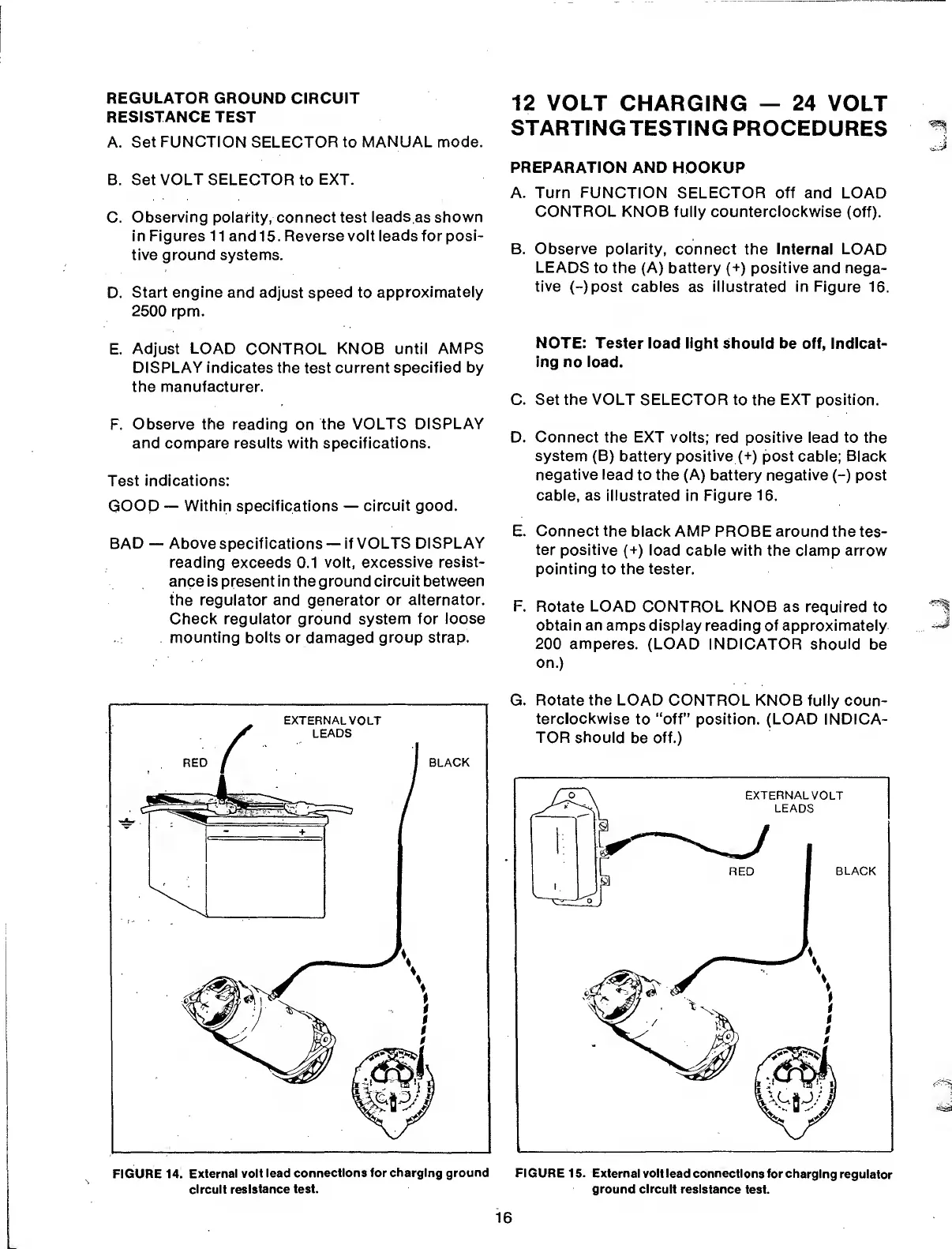
C.
Observing
polarity, connect test
leads as shown
in Figures 11 and 15. Reverse volt
leads
for
posi-
tive ground systems.
D.
Start
engine
and adjust speed to
approximately
2500
rpm.
E.
Adjust LOAD
CONTROL
KNOB until
AMPS
DISPLAY
indicates the test current
specified by
the
manufacturer.
F.
Observe the reading
on
the
VOLTS DISPLAY
and compare results
with
specifications.
Test
indications:
GOOD
—
Within specifications
—
circuit
good.
BAD
—
Above
specifications
—
if VOLTS
DISPLAY
reading exceeds
0.1
volt,
excessive resist-
ance
is
present
in
the
ground circuit between
the regulator and generator or
alternator.
Check regulator
ground system
for
loose
mounting
bolts or damaged
group
strap.
FIGURE 14.
External
volt lead
connections
for charging ground
circuit resistance
test.
12 VOLT
CHARGING
—
24
VOLT
STARTING
TESTING PROCEDURES
PREPARATION AND
HOOKUP
A. Turn FUNCTION SELECTOR off
and LOAD
CONTROL KNOB
fully counterclockwise
(off).
B. Observe polarity,
connect the internal LOAD
LEADS
to the (A) battery
(+)
positive and nega-
tive
(-)post
cables
as illustrated
in
Figure 16.
NOTE:
Tester load light should be
off,
indicat-
ing no load.
C. Set
the VOLT
SELECTOR to
the
EXT position.
D. Connect the EXT volts; red positive
lead
to
the
system (B) battery
positive
(+)
post cable; Black
negative lead
to the (A)
battery negative
(-)
post
cable, as illustrated
in
Figure 16.
E.
Connect
the
black AMP PROBE around the
tes-
ter positive
(+)
load
cable with the clamp arrow
pointing
to the tester.
F.
Rotate
LOAD
CONTROL KNOB as required
to
obtain
an
amps display reading of approximately
200 amperes. (LOAD INDICATOR
should
be
on.)
G.
Rotate
the LOAD
CONTROL KNOB
fully coun-
terclockwise
to
“off”
position.
(LOAD
INDICA-
TOR
should
be off.)
FIGURE
15.
External volt lead
connections for charging
regulator
ground circuit
resistance
test.
16