CHARGING SYSTEM
PINPOINT
TESTS
This section presents a
systematic
method of testing
the
charging
system. It presents the detailed tests that
would
be used
to locate the source of any failures that
may be found
during
area
testing.
OUTPUT
TEST USING TESTER FIELD SELECTOR
NOTE:
This test is
to
determine if alternator
or
voltage regulator is bad. The test is for alternator
charging systems
only. Refer
to
the instructions
of DC charging systems
.
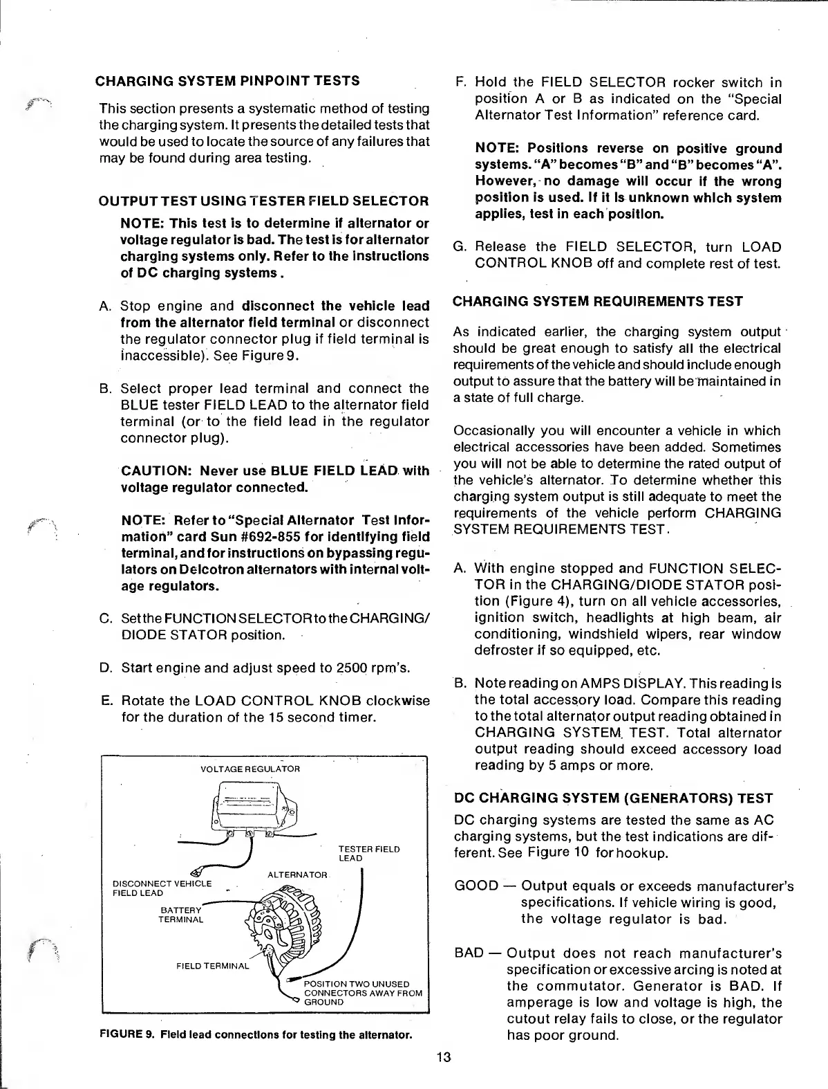
A. Stop
engine
and
disconnect the vehicle
lead
from the alternator
field terminal or disconnect
the
regulator connector plug if field terminal is
inaccessible).
See
Figure 9.
B.
Select proper lead terminal and connect the
BLUE tester FIELD LEAD to the
alternator
field
terminal (or to the
field
lead
in
the
regulator
connector plug).
CAUTION: Never use BLUE
FIELD LEAD with
voltage regulator
connected.
NOTE: Refer to “Special Alternator
Test Infor-
mation” card Sun
#692-855 for identifying field
terminal, and for instructions on bypassing regu-
lators
on
Delcotron alternators with internal volt-
age regulators.
C.
Set the FUNCTION SELECTOR to the CHARG
I
NG/
DIODE STATOR
position.
D. Start
engine and adjust speed to 2500
rpm’s.
E. Rotate
the LOAD CONTROL KNOB
clockwise
for the
duration of the 15 second
timer.
FIGURE
9. Field lead
connections for testing
the alternator.
F.
Hold the FIELD
SELECTOR
rocker switch in
position
A or B
as
indicated
on the
“Special
Alternator
Test
Information”
reference card.
NOTE:
Positions reverse
on positive ground
systems. “A” becomes “B”
and
“B” becomes “A”.
However,
no damage will
occur
if
the wrong
position is
used.
If
it is unknown
which system
applies,
test in each
position.
G.
Release
the
FIELD
SELECTOR,
turn
LOAD
CONTROL KNOB
off and
complete rest
of
test.
CHARGING
SYSTEM
REQUIREMENTS
TEST
As indicated earlier, the
charging system output
should
be
great enough
to
satisfy
all the
electrical
requirements of the
vehicle
and should include enough
output to
assure that the battery will
beirtaintained in
a state of full charge.
Occasionally you will encounter
a vehicle in which
electrical accessories have been added. Sometimes
you
will not
be
able to determine
the rated output of
the vehicle’s alternator. To determine
whether
this
charging system output
is still
adequate to meet the
requirements
of the vehicle perform
CHARGING
SYSTEM REQUIREMENTS TEST.
A. With engine
stopped and FUNCTION
SELEC-
TOR in
the CHARGING/DIODE
STATOR posi-
tion
(Figure
4),
turn
on all vehicle
accessories,
ignition switch,
headlights
at high beam, air
conditioning,
windshield
wipers, rear window
defroster if
so
equipped,
etc.
B. Note reading
on AMPS DISPLAY.
This reading is
the total accessory
load. Compare this reading
to
the
total
alternator output reading
obtained in
CHARGING SYSTEM
TEST. Total
alternator
output reading should
exceed
accessory load
reading
by 5 amps or more.
DC CHARGING
SYSTEM (GENERATORS) TEST
DC charging systems
are tested the same as AC
charging
systems, but the
test
indications
are
dif-
ferent.
See
Figure
10
for
hookup.
GOOD
—
Output
equals
or exceeds manufacturer’s
specifications.
If vehicle
wiring is good,
the
voltage
regulator is
bad.
BAD
—
Output
does not reach manufacturer’s
specification or excessive
arcing is noted at
the commutator.
Generator is BAD.
If
amperage is low
and voltage is high,
the
cutout relay fails to close,
or the regulator
has poor ground.
13
 Loading...