sary within
a
specific
amount of time for
testing to
continue.
“Test Aborted” conditions:
Battery Load tests
—
amps reading falls
below 50
before the
15-second TIMER has timed out.
Starting system tests
—
starter
current
drops below
50
amps after the test
has begun.
Diode Stator/Charging system tests
—
1.)
current
value
is less
than 10 amps once the test
begins.
2.)
engine rpm value falls below
2000
once
test begins.
TEST ABORTED CONDITIONS
are also discussed
more in-depth in
specific TESTING MODES
sec-
tions of this
manual.
INTEGRAL
FAN
The
INTEGRAL FAN
is
activated
whenever the VAT
60’s
carbon pile
assembly becomes too warm.
PRELIMINARY INSPECTION
Before any testing is done,
a
series
of
visual
inspec-
tions
should
be
performed. These
inspections should
include
drive
belts,
charging system components,
battery,
and
associated
cables.
Belt Inspection
1.
Inspect condition and
tension of
drive
belts.
-2.
If necessary, replace and/or adjust
to proper
tension before proceeding
with tests.
Charging System Components Inspection
1. Inspect condition,
mounting, wiring and con-
nections of alternator and
regulator.
2. Correct any discrepancies
found.
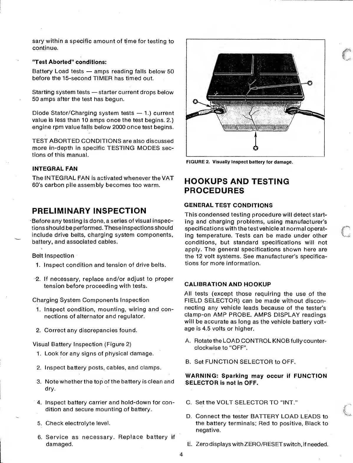
Visual Battery Inspection
(Figure
2)
1. Look for any signs of
physical damage.
2.
Inspect battery posts, cables, and clamps.
3. Note whether the top
of the battery is clean and
dry.
4. Inspect battery carrier and
hold-down
for con-
dition and secure
mounting
of
battery.
5. Check electrolyte
level.
6. Service as
necessary.
Replace battery
if
damaged.
i
FIGURE 2. Visually Inspect
battery for
damage.
HOOKUPS AND
TESTING
PROCEDURES
GENERAL
TEST
CONDITIONS
This
condensed testing procedure will
detect start-
ing
and
charging
problems, using
manufacturer’s
specifications with
the test
vehicle at normal
operat-
ing temperature.
Tests can be made under other
conditions, but standard
specifications will not
apply. The general
specifications shown here
are
the 12
volt
systems. See manufacturer’s specifica-
tions for more information.
CALIBRATION
AND HOOKUP
All tests (except
those requiring the
use of the
FIELD SELECTOR)
can be made without discon-
necting any vehicle
leads
because
of the tester’s
clamp-on
AMP PROBE. AMPS
DISPLAY readings
will
be accurate as long
as the vehicle
battery volt-
age is 4.5 volts
or higher.
A. Rotate the LOAD
CONTROL KNOB fully counter-
clockwise to
"OFF”.
B. Set FUNCTION
SELECTOR
to
OFF.
WARNING:
Sparking
may
occur if FUNCTION
SELECTOR is
not in OFF.
C. Set the VOLT
SELECTOR TO “INT.”
D. Connect the
tester BATTERY LOAD LEADS
to
the battery
terminals; Red to positive, Black
to
negative.
E.
Zero displays
with ZERO/RESET
switch, if needed.
4
 Loading...