A. Set
the VOLT SELECTOR
to
EXT.
B.
Connect test leads as
shown in Figures
5
and 6
for type
of circuit being tested.
C. Disconnect lead
from coil secondary
(tower) to
prevent engine from
starting
during test.
D.
Crank engine
and observe VOLTS
DISPLAY
reading while cranking. Reading
should
bewithin
manufacturer’s specifications.
Test indications:
GOOD
—
Less than 0.4 volt
(6
volt system)
Less than 0.5 volt
(12
volt
system)
go to Ground Circuit Resistance
Test.
BAD
—
More than 0.4 volt
(6
volt system)
More
than 0.5 volt
(12
volt
system)
NOTE:
To locate the cause
of the excess volt-
age drop, move the EXT VOLT
LEAD
on the
starter
progressively toward
the battery. With
each move,
crank engine and read voltage.
When
a noticeable decrease in the
voltage read-
ing
is
observed, the
trouble is located
between
that
point and the
preceding point tested. It will
be either a damaged
cable or poor connection,
an undersized wire, or
possibly a bad
contact
assembly
within
the solenoid.
Values of maximum
voltage drops for
the cranking
circuit
are as follows:
-
Each cable
—
0.1 volt
(6
volt) 0.2 volt
(12
volt).
Each
connection
—
0.0 volts both
6
and
12 volt
systems.
Starter Solenoid
Switch
—
0.3 volts both
6 and 12
volt systems.
FIGURE
5. External volt lead
connections where starter solenoid
Is on the starter.
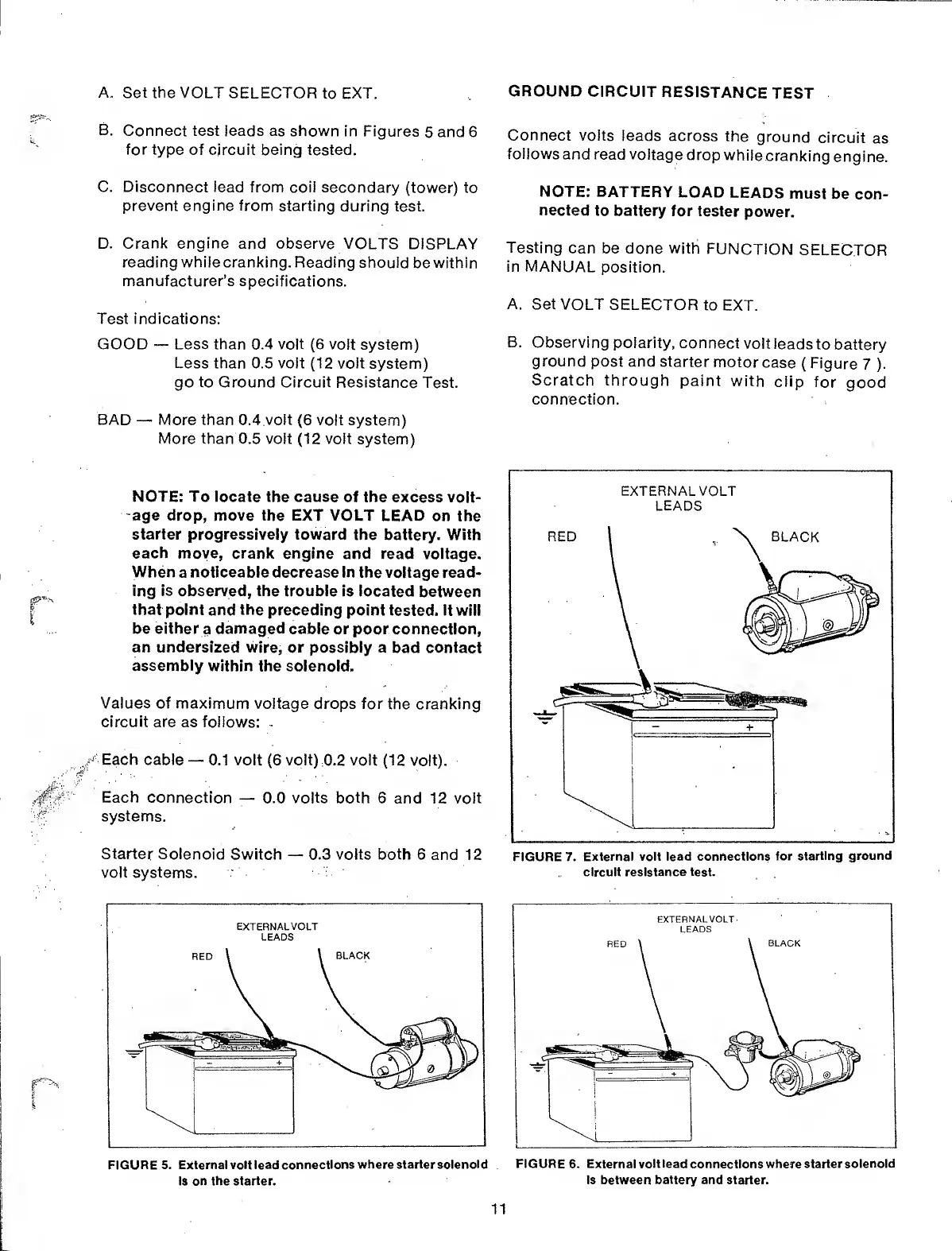
GROUND
CIRCUIT
RESISTANCE
TEST
Connect
volts
leads across
the
ground
circuit
as
follows
and read
voltage
drop
while
cranking
engine.
NOTE:
BATTERY
LOAD
LEADS
must
be
con-
nected
to battery
for
tester
power.
Testing
can be done
with
FUNCTION
SELECTOR
in MANUAL
position.
A.
Set VOLT
SELECTOR
to
EXT.
B.
Observing
polarity,
connect
volt
leads
to battery
ground
post and
starter
motor
case
(
Figure
7
).
Scratch
through
paint
with
clip
for
good
connection.
FIGURE 7.
External volt lead connections
for
starting ground
circuit resistance test.
FIGURE 6.
External
volt lead
connections where
starter solenoid
is between battery and starter.
11