C.
Crank engine
and observe
VOLTS DISPLAY
reading
while cranking.
Reading
should be within
manufacturer’s
specifications.
Test indications:
GOOD
—
Less
than
0.1 volt
(6
volt
system)
Less than 0.2 volt
(12
volt
system)
go
to
Insulated Circuit
Resistance Test.
BAD
—
More than 0.1 volt
(6
volt
system)
More than 0.2 volt
(12
volt system)
indicates the
presence of a poor ground
circuit connection.
Could be a loose
starter
motor mounting boltorabad batteryground
terminal
post connector, or a
damaged
or
undersized ground system
wire
from bat-
tery
to
engine
block.
Isolate the
cause
of excess voltage
drop in the same
manner recommended
in the Starter System
Insu-
lated Circuit Test.
SWITCH
CIRCUIT
RESISTANCE
TEST
High resistance
in
the solenoid switch circuit will
reduce the current flow through the solenoid wind-
ings
which
can cause
improper
functioning of the
solenoid. In
some
cases of high
resistance, it may
not
function at all. Improper
functioning of
the
solenoid switch will generally result
in
burning of
the solenoid switch contacts causing a high resist-
ance
in
the starter
motor circuit.
Test
Procedure
Check vehicle wiring diagram,
if
possible, to identify
the
solenoid circuit components. These are usually
the ignition switch, the automatic
transmission
neu-
tral switch, and the starter
solenoid winding.
In
some instances, a
separate starter relay
is
also used,
and
the contacts in this starter relay should be
checked
for
excessive resistance just
as
the sole-
noid switch
is
tested.
NOTE: BATTERY LOAD
LEADS must be con-
nected to
battery
for
tester power.
Testing
can be
done with
FUNCTION SELECTOR
in
MANUAL position.
A.
Set the
VOLT SELECTOR
to EXT.
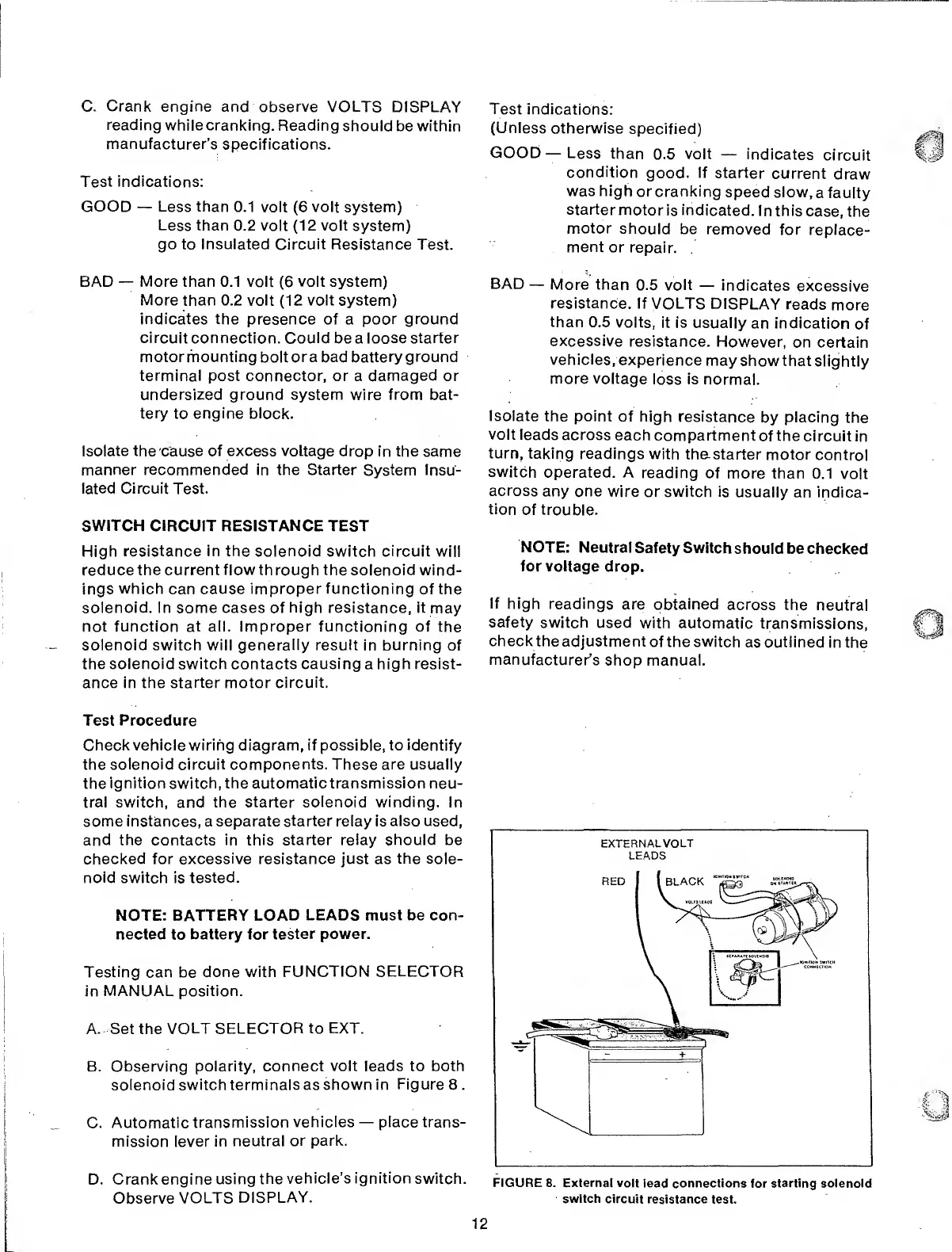
B. Observing polarity,
connect volt leads to both
solenoid
switch terminals as shown in
Figure
8 .
C.
Automatic
transmission
vehicles
—
place trans-
mission lever in
neutral
or park.
D. Crank engine
using
the
vehicle’s ignition
switch.
Observe
VOLTS
DISPLAY.
Test
indications:
(Unless
otherwise
specified)
GOOD
—
Less
than
0.5
voit
—
indicates
circuit
condition
good.
If
starter
current
draw
was high
or cranking
speed slow,
a faulty
starter
motor
is indicated.
In this
case,
the
motor
should be
removed for
replace-
ment
or
repair.
BAD
—
More than
0.5 volt
—
indicates
excessive
resistance.
If
VOLTS
DISPLAY reads
more
than
0.5
volts,
it
is
usually
an indication
of
excessive
resistance.
However,
on certain
vehicles,
experience
may
show that
slightly
more voltage
loss is
normal.
Isolate
the point
of high
resistance
by
placing
the
volt
leads
across
each
compartment
of the circuit
in
turn,
taking readings
with
th&starter
motor
control
switch
operated.
A
reading
of more than
0.1
volt
across
any one
wire or switch is
usually
an indica-
tion
of
trouble.
NOTE:
Neutral
Safety Switch
should
be
checked
for voltage
drop.
If
high
readings
are obtained
across the
neutral
safety
switch used
with automatic
transmissions,
check the
adjustment of the switch
as outlined
in
the
manufacturer’s
shop manual.
EXTERNAL
VOLT
LEADS
FIGURE 8. External volt
lead connections
for
starting solenoid
switch
circuit resistance
test.
12
 Loading...