NOTE: The circuit
resistance, as indicated
by
the above
VOLTS
DISPLAY reading, is
equal to
the total of both the
Insulated Circuit
and
the
Ground
Circuit Voltage losses.
In general, on
alternator systems, the
following
specifications
apply:
American
Motors 0.65 volt MAX
Chrysler Motors
0.9 volt
Ford
Motor
Company 0.4 volt w/lnd Lamp
0.8
volt w/Ammeter
General Motors
0.65 volts
INSULATED CIRCUIT
RESISTANCE TEST
If voltage loss
in the preceding test (System Circuit
Resistance)
exceeds the specified
amount,
an exces-
sive
resistance
is present within the charging circuit.
That is,
within the wiring harness, connections, regu-
lator and
vehicle ammeter if used.
The excessive
res-
istance can take the form
of LOOSE OR CORRODED
CONNECTIONS at output terminal of generator or
alternator, armature terminal of
regulator,
back of
ammeter or
battery terminal of the starter solenoid
battery
cable connections, faulty wiring from genera-
tor to regulator to ammeter or
ammeter
to
starter
solenoid,
burned or oxidized cutout relay contacts, or
poor
electrical connections between the generator
or
alternator and the
engine.
To
isolate
the point of
excessive resistance, proceed with the following
charging system resistance test.
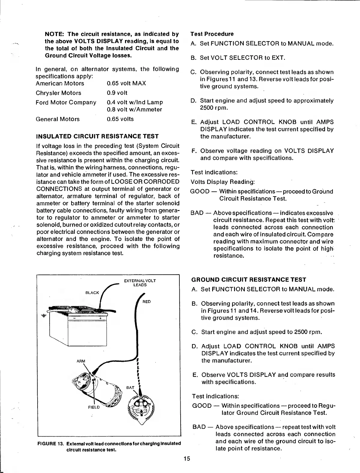
FIGURE
13. External volt lead
connections for
charging
insulated
circuit resistance
test.
Test Procedure
A. Set FUNCTION SELECTOR to MANUAL mode.
B. Set VOLT SELECTOR to EXT.
C.
Observing
polarity,
connect test leads as shown
in Figuresll and
13.
Reverse volt leads for posi-
tive
ground
systems.
D.
Start
engine
and adjust
speed to approximately
2500 rpm.
E. Adjust
LOAD CONTROL KNOB
until AMPS
DISPLAY indicates the test current
specified by
the
manufacturer.
F.
Observe voltage reading on VOLTS DISPLAY
and compare
with
specifications.
Test
indications:
Volts
Display Reading:
GOOD
—
Within specifications
—
proceed
to Ground
Circuit
Resistance
Test.
BAD
—
Above specifications
—
indicates
excessive
circuit resistance. Repeat
this test with
volt
leads connected across
each connection
and each wire of insulated circuit.
Compare
reading with maximum
connector and wire
specifications to isolate
the point
of
high
resistance.
GROUND
CIRCUIT
RESISTANCE TEST
A. Set FUNCTION
SELECTOR
to
MANUAL
mode.
B. Observing polarity, connect test
leads
as
shown
in
Figuresll and
14.
Reverse volt leads for posi-
tive ground
systems.
C.
Start engine and adjust speed to 2500 rpm.
D. Adjust LOAD
CONTROL KNOB until AMPS
DISPLAY indicates the test current
specified
by
the manufacturer.
E.
Observe VOLTS DISPLAY and
compare results
with
specifications.
Test
indications:
GOOD
—
Within
specifications —
proceed
to Regu-
lator Ground Circuit Resistance Test.
BAD
—
Above specifications
—
repeat test with volt
leads
connected across
each connection
and
each
wire of the
ground
circuit to iso-
late point of resistance.
15
 Loading...