6 Electrical Connection User Manual
18
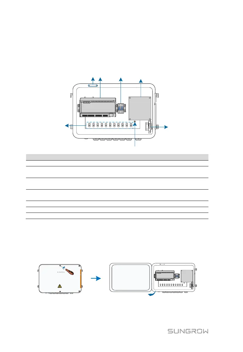
6.2 Internal Structure
The internal structure of the COM100 is shown in the following figure.
Logger1000A or Logger1000B
Switch-mode power supply and surge protection device, 24Vdc power
supply
Micro circuit breaker, used to connect/disconnect the external 220Vac
power supply
Lighting device, turn on the light before opening the front cover of the
cabinet for ease of night maintenance
Cable tie buckle, used for binding cables
6.3 Preparation Before Cable Connection
Step 1 Release the 4 screws on the front side of the COM100 and open the
front cover of the cabinet, as shown in the figure below.
Step 2 Turn the internal power switch of the COM100 to the "OFF" position to
ensure the COM100 is voltage-free.