8 Grid Dispatching Function User Manual
28
The corresponding power dispatching function is available only when
the inverter supports active power control, power factor control, and
reactive power regulation!
For details, refer to the inverter user manual or consult the local
retailers.
8.2 Interface Description
The COM100 is equipped with digital control ports and analog control ports for
receiving digital instructions and analog instructions sent from the grid
dispatching center.
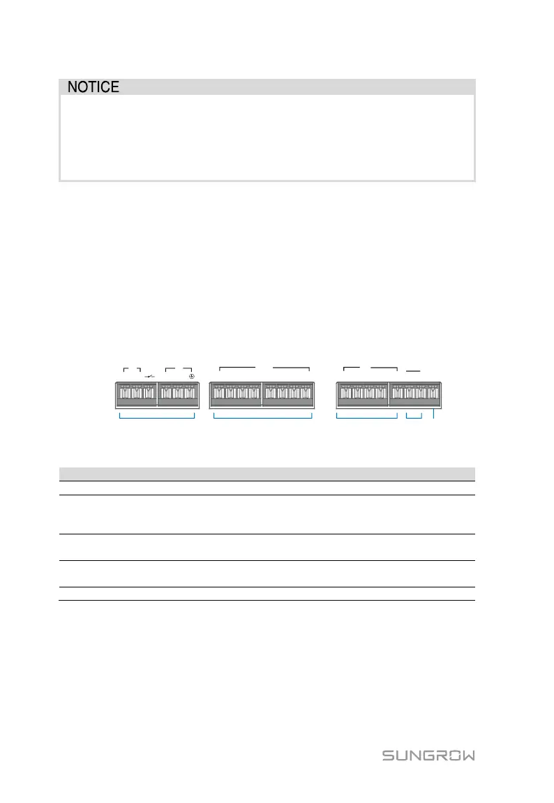
8.2.1 Digital Control Interface
Digital control interface is located at the bottom of the Logger1000 inside the
COM100.
1+ 1- 2+ 2-
AI/DI
3+ 4+3- 4-
1
2
3 4
DI
DRM
5 R C
24V
OUT
DI
+
-
24V
IN
+
-
0V
A
B C D
E
Tab. 8-1 Digital control interface signal definition
Switch for enabling the AI/DI function
AI/DI
(1+, 1-, 2+, 2-
3+, 3-, 4+, 4-)
4 analog input channels, and can be
switched to 4 dry contact signal
channels.
5 independent input dry contact signal
channel
Works together with the DI1 to DI4 to
achieve the DRM function
Input dry contact signal ground
Wireless receiver controller (Ripple Control Receiver)
Wiring between the COM100 and the Ripple Control Receiver is as follows: