Configuration circuitboard
COM
NC
NO
Emergency Stop
COM
Fault Alarm
COM
NC
NO
COM
RS
485
RS
485
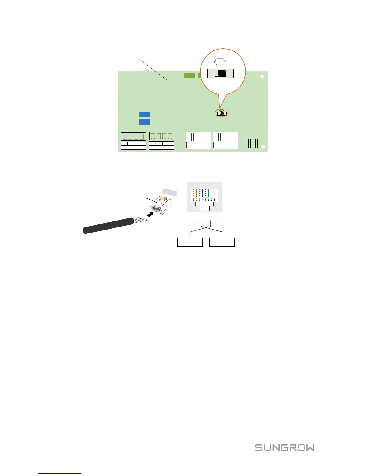
120Ω terminating
resistor switch
Default
OFF
ON
RJ45 interface
For RJ45 Connection the pins definitions are shown below.In Ethernet cable, Pin 3
white-green cable defines RS485- B while Pin 6 green cable defines RS485+ A.
1 2 3 4 5 6 7 8
RS485+ A
RS485- B
Pin 3 and Pin 6 are used for
communication
.
-
Pin 3 to RS485- B
- Pin 6 to RS485
+ A
Corresponding Relationship Between
Cables and Pins:
Pin 1: White-orange; Pin 2: Orange;
Pin 3: White-green; Pin 4: Blue;
Pin 5: White-blue; Pin 6: Green;
Pin 7: White-brown; Pin 8: Brown.
RJ45 Port
RJ45 plug
1
----8
3-7 Completing Installation
Seal the gaps between the cables and the glands inside the lower part of the
cabinet by fireproofing mud. Inspect before commissioning and reassemble the
front cover of the connection cabinet.
 Loading...