COOLANT SYSTEM
Oil Flow
TO CHECK the oil flow, point oil jets to direct flow
into Work Tray. Turn machine ON. Open Total
Volume Control Valve slightly. Adjust Individual
Oil jet Control Valves for desired volume of oil,
opening Total Volume Valve further as needed. Total
Volume Valve may then be used to shut entire
supply off, leaving individual settings unchanged.
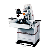
TO ADJUST the oil flow, check first to be sure oil
level covers the pump housing. Make sure the oil
pump belt is taut and in good condition. Also check
screen on oil pump to make sure it is not clogged
(see Figure 4-10).
NOTE: If the machine is low on oil, order more
Sunnen Industrial Honing Oil. DO NOT ADD
KEROSENE, CUTTING FLUIDS, OR ANY
OTHER FLUID TO THE OIL THAT'S LEFT - IT
WILL BE RUINED. If you must operate the machine
before you receive your new oil, temporarily drain
and remove Sediment Tray. Place a large chunk of
metal in the reservoir if necessary to raise the oil
level above the pump inlet - but remember this is a
temporary expedient, and remove the chunk of metal
when you refill the reservoir. Also, reinstall the
Sediment Tray.
Oil Pump Belt
TO CHECK the oil pump belt, it should be just tight
enough to turn the oil pump pulley without slipping.
If oil pressure falls excessively when spindle
rotates, oil pump belt may be too loose.
TO ADJUST the oil pump belt, make sure reservoir
is pushed back into the machine as far as it will go.
If belt needs adjusting, loosen Clamp Knob in top
of Pump Bracket and move Bracket as needed.
Retighten Clamp Knob.
Installing New Oil Pump Belt (Part No. MB-2292)
Remove left rear cover
(see Figures 4-10 and 4-11).
Loosen Clamp Knob in top of Pump Bracket.
Remove oil pump belt. Thread new oil pump belt
around drive pulley, idler pulleys, and pump pulley.
Adjust tension and tighten clamp knob.
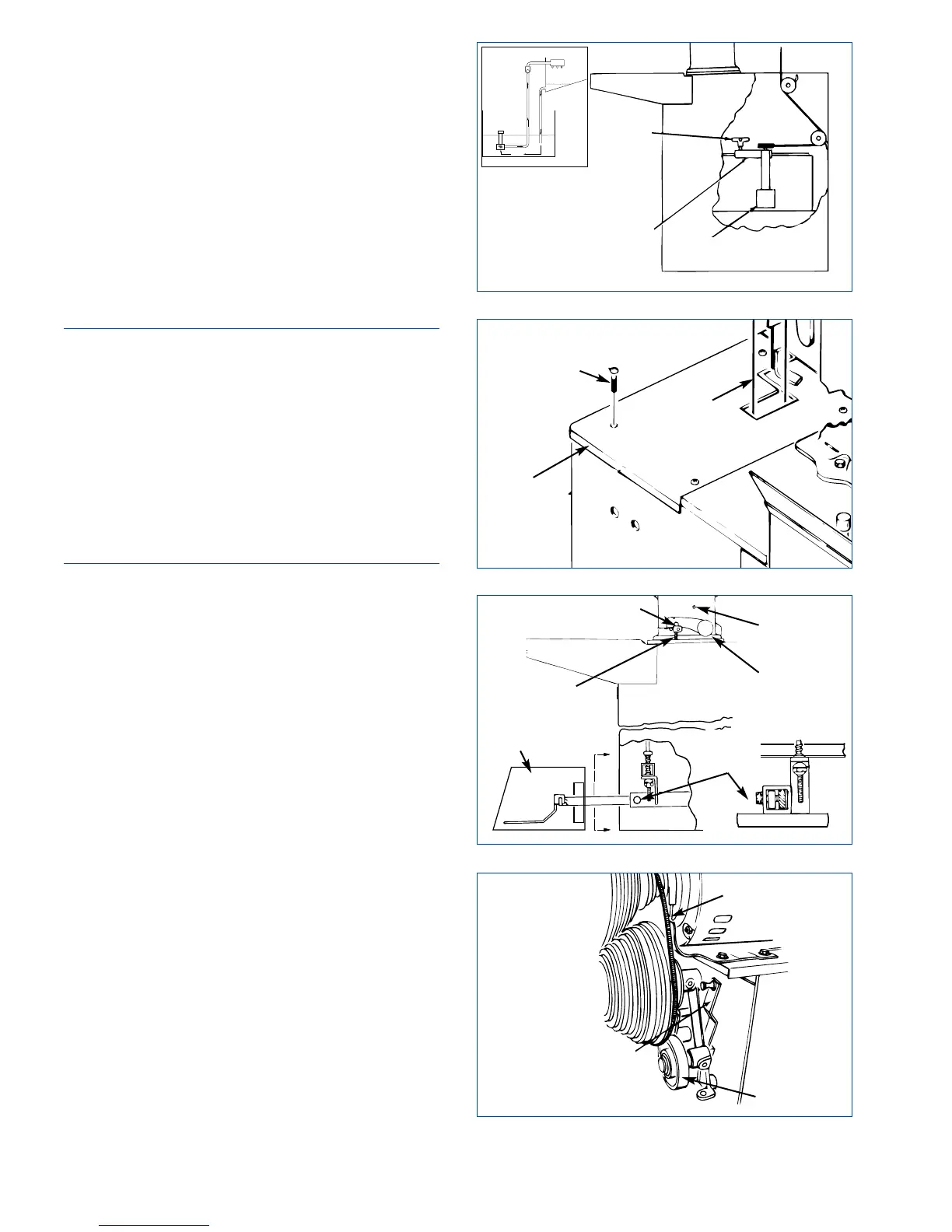
PEDAL ADJUSTMENT
The Pedal can be adjusted in or out; up or down;
and for standing or sitting. Pedal when fully
depressed MUST be at least 6 mm (.25 in.) from
floor and not higher than 50 mm (2 in.) from floor.
To check: Crank Arm must hit Lower Stop Pin when
Pedal is between 6-13 mm (.25-.50 in.) from floor.
When Pedal is released, Crank Arm should hit Upper
Stop Pin.
To adjust, proceed as follows
(see Figure 4-12):
22
FIGURE 4-13, Motor V-Belt
V-BELT
TENSION
RELEASE
LEVER
IDLER
FIGURE 4-10, Pump
FIGURE 4-11, Belt
FIGURE 4-12, Pedal
CLAMP
KNOB
PUMP
BRACKET
PUMP
SCREEN
BELT
LEFT
REAR
COVER
SCREW
UPPER
STOP PIN
CRANK
ARM
ADJUSTING
SCREW
LOWER
STOP PIN
PEDAL
CLAMP
SCREW
PEDAL
COVER
SEE APPENDIX D