REPLACE SPINDLE DRIVE BELT
To inspect and replace Flat Spindle Drive Belt,
proceed as follows
(see Figure 4-15):
WARNING
Turn electrical power OFF at main buss box or
main power source when performing any
maintenance not requiring power.
1. Turn OFF all electrical power to machine.
2. Loosen safety latch pin, raise belt cover latch
and open belt guard.
NOTE: Turn Disconnect Switch on left side of Belt
Guard to OFF position, then open doors.
3. Inspect Spindle V-Belts for signs of wear or
damage. Replace as required, proceed with step 4.
4. Remove Oil Pump Belt from motor pulley and
carefully drape it over side of machine so it doesn't
get oil on it or come off the idlers or the oil pump
pulley (Installing New Oil Pump Belt).
5. Pull tension release lever
(see Figure 4-16)
down.
5. Remove Motor V-Belt. Slip Motor V-Belt off
Lower Cone Pulley.
6. Remove two Bolts and Nuts securing Feed Arms
as follows:
Insert 3/16 in. (5 mm) rod in Cross Hole in Feed Rod
to keep Feed Rod from turning
(refer to Figure 4-16).
Using 5/16 in. hex wrench, remove Screw and
washer from Thrust Assembly.
7. Turn Feed Dial counterclockwise all the way
until Adjusting Nut Assembly is clear of Feed
Screw.
8. Separate Arms and remove. Pull Feed Arm
Assembly with Thrust Assembly off Feed Rod.
9. Push tension release lever up and remove old flat
drive belt.
10. Remove old Flat Spindle Drive Belt and install
new Belt.
11. Ensure projection on Adjusting Nut Assembly is
pointed upward; then, install Feed Arms and secure
with Nuts and Bolts removed in step 6.
Reassemble Feed Arm Assembly to Feed Rod by
engaging Adjusting Nut Assembly with Feed Screw
and turning Feed Dial clockwise while inserting
Feed Rod into Thrust Assembly. Projection on
Adjusting Nut Assembly must point upward.
Bearing retaining screws in Thrust Assembly must
face back of machine head.
12. Pull tension release lever down.
13. Install Motor V-Belt. Align on Lower Cone
Pulley and motor pulley.
14. Pull out and up on Idler Handle.
15. Replace Oil Pump Belt.
16. Close and secure belt guard.
17. Turn ON power.
ADJUST BRAKE STRAP
To check brake operation, observe spindle when
pedal is released, the honing machine spindle
should stop instantly.
Adjusting Brake Strap Tension will increase or
decrease time required for spindle to come to a
complete stop after honing operation is completed.
Adjust tension as follows
(see Figure 4-17):
WARNING
Turn electrical power OFF at main buss box or
main power source when performing any
maintenance not requiring power.
1. TURN OFF all electrical power to machine.
2. Loosen safety latch pin, raise belt cover latch
and open belt guard.
NOTE: Turn Disconnect Switch on left side of Belt
Guard to OFF position, then open doors.
3. Loosen Socket Head Capscrew (E) in Brake
Cam, using 1/4" hex wrench (see Figure 4-19).
4. Rotate Brake Cam until Brake Strap is loose.
5. Loosen 7/16" Locknut (A) on Brake Adjusting
Screw.
6. While holding Brake Cam up as far as possible,
adjust Brake Adjusting Screw (D) until screw head
just contacts Ridge on Brake Lever. Then tighten
Locknut.
7. Rotate Brake Cam counterclockwise to take up
slack in Brake Strap; and Brake Lever is horizontal
(refer to Figure 4-19). Then tighten Capscrew (E).
8. Close right side of Belt Guard and reinstall
Button Head Capscrew removed in step 4.
24
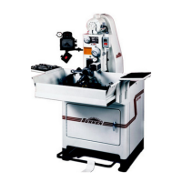
FIGURE 4-16, Tension Release Lever
TENSION
RELEASE
LEVER