Sunsation Instructions Manual
Pantone 1375 C
RGB: 255, 158, 27
CMYK: 0, 38, 89, 0
HEX: #FF9E1B
Gray 49%
20
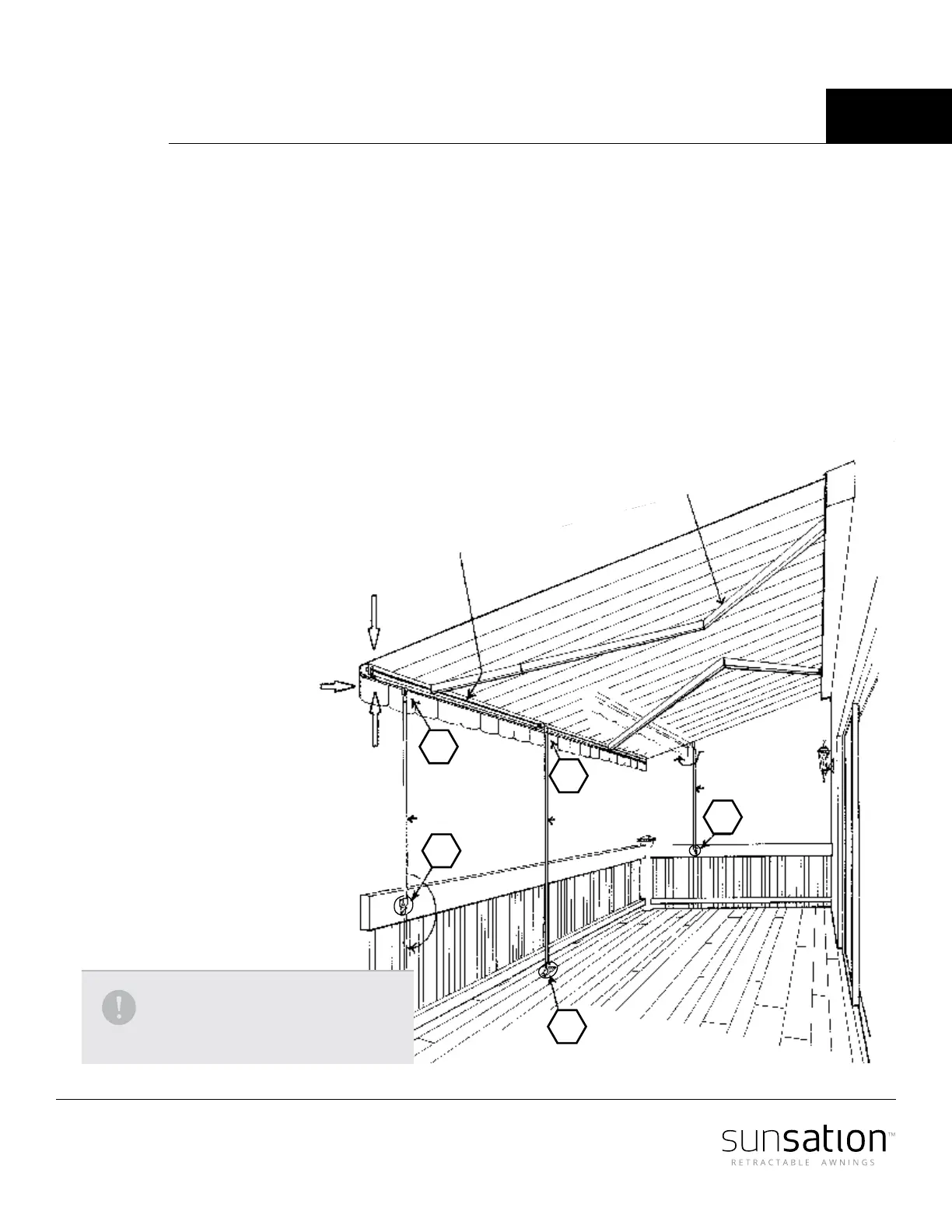
Support brace
A1 Top end of pole brace secured to bottom slot channel of existing front linear
aluminum extruded channel.
A2 Lower end secured to a existing rail or wall.
B1 Top end of pole brace secured to rear slot channel of existing canopy front linear
aluminum extruded channel.
B2 Lower end secured to an existing ground building surface.
C During the partial projection of a existing awning canopy the lower end of pole brace
may be secured to ground surface or side rail or wall.
Pole brace
Wind stress
Typical existing spring loaded
projecting arms
Typical existing canopy
front linear channel
Partial awning
canopy projection
Pole brace
Pole brace
B2
A2
A1
B1
C
A minimum of 2 pole brace units
are required 1 per every existing
projecting awning canopy arm.