Website: www.sunsynk.com E-mail: sales@globaltech-china.com
17
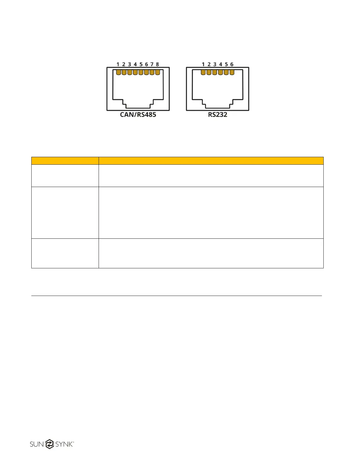
4.7.3 Port RS485 and RS232
Figure 5 - CAN/RS485 and RS232 connections
Description
CAN
Pin 4: CAN-H
Pin 5: CAN-L
Pin 1, 3, 6, 7, 8: NC
RS485
Pin 1: RS485B
Pin 2: RS485A
Pin 3: GND
Pin 6: GND
Pin 7: RS485B
Pin 8: RS485A
Pin 4, 5: NC
RS232
Pin 3: BMS transmit; Computer receiver
Pin 4: BMS receiver; Computer transmit
Pin 5: GND
Pin 1, 2, 6: NC
5. BATTERY OPERATION AND COMMISSIONING
Before turning on the batteries, please check the installation:
Check the polarities of the batteries.
Check if there are no damaged cables.
Check for local installation compliance.
Check if appropriate air flow is provided to the set.
5.1. System Power ON
Installation (including DC cable, communication wire connection, dialer switch, and circuit breaker) is
properly down.
Press Power Switch button and then the external circuit breaker, the green LED should be twinkling
and then turn into function mode. (system status can be red from LED signal, as shown below)
 Loading...
