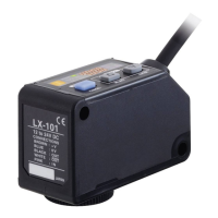
Housing
q 0V
w Comparative output
e
+
V
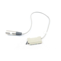
n ASSEMBLY OF CONNECTOR
q Using a suitable cable having the following specifications, prepare its end
with a stripper, etc., as given in the figure below.
Further, the cable extension can be 100m or less with 0.3mm
2
, or more, cable.
m FUNCTIONAL DESCRIPTION
, ERROR MESSAGES
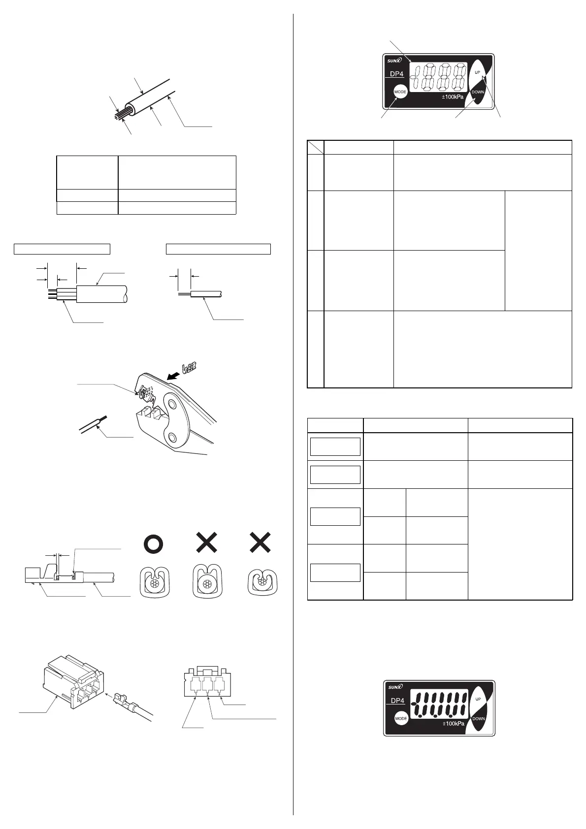
. ANALOG BAR DISPLAY
䢇 Pressure changes are displayed in an analog fashion by using LCD bar. Hence,
any sudden changes in pressure can be detected at a glance.
䢇 The analog bar display shows the measured pressure, in steps of 14% F.S.
approx.
w Setting the connector pin in the groove of the exclusive crimp tool as shown
in the figure below, insert the lead wire into the connector pin and crimp.
e After crimping, make sure to confirm that the crimping is proper, as shown in
the figure below.
In case the crimping is incorrect, cut the cable and repeat the procedure from
Step q.
r As shown in the figure below, insert the connector pin till the end of the hous-
ing.
After inserting, make sure to confirm that the locking is proper by pulling
lightly (10N or less) at the cable.
• Pin position
Note:
Do not reuse a connector pin which has been crimped once or inserted into the housing,
as its performance cannot be guaranteed.
Please procure the optional connector (CN-63) (10 Nos./set) or the recommended
product.
A connector attached cable (CN-63-C2) (cable length: 2m) is also available.
In case of cabtyre cable In case of single lead wire
20mm
2.2mm
2.2mm
Sheath
Lead wire
Lead wire
1
432
<Recommended>
Crimping tool: YC-690R manufactured by J.S.T. MFG CO., LTD.
Connector pin: BXA-001T-P0.6 manufactured by J.S.T. MFG CO., LTD.
<Recommended>
Housing: XAP-03V-1 manufactured by J.S.T. MFG CO., LTD.
Cause
Overcurrent due to short-circuit.
Pressure is being applied during zero-
point adjustment.
Vacuum
pressure type
Applied pressure exceeds
the lower limit (reverse
pressure) of displayable
pressure range.
Applied pressure
exceeds the upper
limit of displayable
pressure range.
Vacuum
pressure type
Applied pressure
exceeds the upper
limit of displayable
pressure range.
Applied pressure exceeds
the lower limit (reverse
pressure) of displayable
pressure range.
Positive pressure
and compound
pressure types
Positive pressure
and compound
pressure types
Corrective action
Switch off the power supply and
check the load.
Applied pressure at the pressure
port should be brought to atmos-
pheric pressure and zero-point
adjustment should be done again.
Applied pressure should be brought
within the rated pressure range.
Error message
E - 3
E - 1
- - -
-
- - -
Lead wire
Connector pin
Core wire
should be visible
0.5 to 1mm
Connector pin Lead wire
Lead wire diameter
0.16 to 0.32mm
2
(AWG 25 to 22)
φ1.2 to φ1.8mm
Conductor
cross-section area
(Note)
Wire material
Tin plated, soft, twisted copper wire
Lead wire
Lead wire diameter
Conductor
cross-section area
• Cable specifications
3
1
/
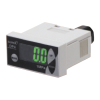
2
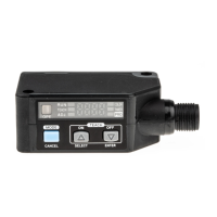
digit LCD display
q
with red and
green backlight
Description Function
• Displays measured pressure, settings, error messages and
key-protect status.
• Red display when comparative output is ON.
• Green display when comparative output is OFF.
• In the initial setting mode and supple-
mentary setting mode, pressing the
key changes the setting item.
•
In the pressure value setting mode,
pressing the key changes the set value.
•
In the sensing mode, pressing the key
continuously for 4 sec., or more, dis-
plays the peak hold value.
w
UP key
e
DOWN key
r
MODE key
• In the pressure setting mode, pressing the key changes the
setting item.
• In the sensing mode, pressing the key continuously for 4 sec.,
or more, can set/cancel the key-protect.
•
In the sensing mode, pressing both UP key and MODE key
simultaneously changes the mode to the initial setting mode.
Whereas, pressing both DOWN key and MODE key simulta-
neously changes the mode to the supplementary setting
mode.
• In the sensing
mode, if both keys
are simultaneously
pressed continu-
ously, zero-point
adjustment is done.
• In the initial setting mode and supple-
mentary setting mode, pressing the
key changes the set conditions.
•
In the pressure value setting mode,
pressing the key changes the set value.
•
In the sensing mode, pressing the key
continuously for 4 sec., or more, dis-
plays the bottom hold value.
()
⁄0 MEMORY BANK FUNCTION
䢇 The memory bank function allows two types of set values to be stored: Set
Values 1 to 3 (P-1 to P-3) and Set Values 4 to 6 (P-4 to P-6).
This makes it possible to the change set values quickly.
(Refer to ‘⁄2 SETTING, Pressure value setting mode’.)
Note: If the wire length is 2m or more, use 0.3mm
2
, or more,
cable.
Ramco Innovations (800) 280-6933 www.sunxsensors.com
 Loading...