SG Series Boilers – Installation and Service Manual
16
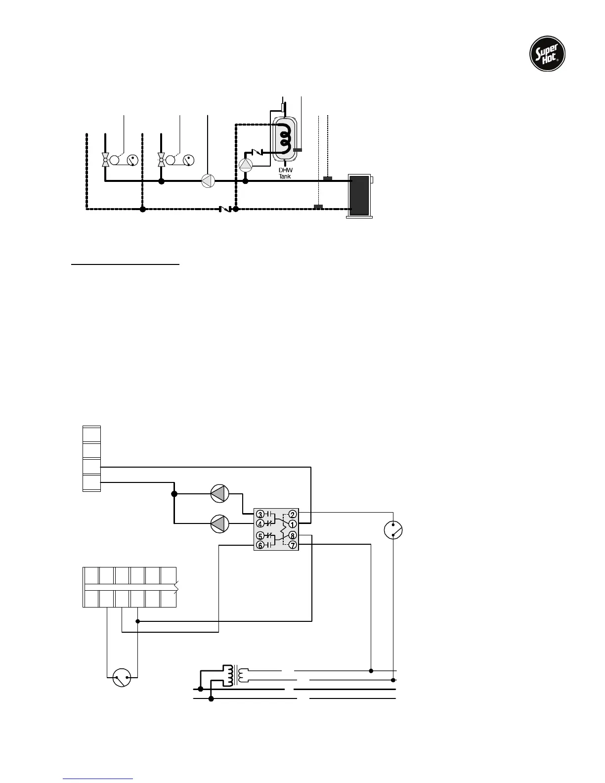
Figure 4 – Typical piping diagram in Mode 4
Sequence of Operation
Thermostat (T1) closed - Thermostat creates a Heat Demand resulting in a boiler target based on the
outdoor reset settings. The boiler pump (Pump1) operates.
DHW Aquastat (A1) closed - DHW Aquastat creates Setpoint DHW Demand and activates external
pump relay. The external pump relay causes the following actions:
1) Power for the boiler pump (Pump1) is broken. Pump1 does not operate.
2) Power for the DHW pump (Pump2) is made. Pump2 operates.
3) Setpoint DHW Demand creates a boiler target based on the higher requirement of the
outdoor reset and reset override setting.
2S
1S
1T1T
1A
1Pump
2Pump
MM
MODE 4 ONLY
(Outdoor reset and reset override)
S1 = Boiler Outlet Sensor 071
S2 = Boiler Inlet Sensor 071
Pump1 = Boiler Pump
Pump2 = DHW Pump
A1 = DHW Aquastat
T1 = Thermostat
A1
Pump 1
Pump 2
ramket
300yaleR
42V
021V )ca(
lanretxE
IIssalC
remrofsnarT
N
L
C
R
L1
L2
P1
P2
C HT ST R FS FS
123456
T1
Figure 5 – Wiring diagram illustrating use of an External Relay to control pump operation