SG Series Boilers – Installation and Service Manual
20
d) Place in operation the boiler being inspected. Follow the lighting instructions. Adjust the thermostat
so the boiler will operate continuously.
e) Test for spillage at the draft hood relief opening after 5 minutes of main burner operation. Use the
flame of a match or candle, or smoke from a cigarette, cigar or pipe.
f) After it has been determined that each appliance remaining connected to the common venting system
properly vents when tested as outlined above, return doors, windows, exhaust fans, fireplace
dampers and any other gas burning appliance to their previous conditions of use.
g) Any improper operation of the common venting system should be corrected so the installation
conforms with the National Fuel Gas Code, ANSI Z223.1 and/or CAN/CGA Installation Codes. When
re-sizing any portion of the common venting system, the common venting system should be resized
to approach the minimum size as determined using the appropriate tables in Part 11 of the National
Fuel Gas Code, ANSI Z223.1 and/or CAN/CGA Installation Codes.
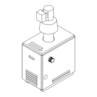
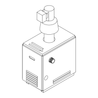
2.8 AUTOMATIC VENT DAMPER
All boilers with an input of 300,000 Btu/h and under are supplied with an automatic vent damper. The
following instructions must be observed:
• The automatic vent damper should be installed at the top of the factory supplied draft hood (Figure 1 -
Alternate 3). No modifications to the automatic vent damper are permitted.
• The venting system must be arranged so that only the boiler is served by the automatic vent damper
with which it was supplied.
• Connect the wiring harness from the boiler to the automatic vent damper as indicated on the supplied
wiring drawings.
• The automatic vent damper position indicator should be clearly visible after installation.
• A minimum clearance of not less than 6 inches (153 mm) must be maintained between the automatic
vent damper device and combustible construction. Provision must be made for service access to the
automatic vent damper.
• The automatic vent damper must be in the open position when the boiler's main burner is operating.
• For orientation other than vertical, refer to automatic vent damper installation instructions
2.9 BLOCKED VENT AND FLAME ROLL-OUT SAFETY SWITCHES
All boilers with an input of 300,000 Btu/h and under are equipped with blocked vent and flame roll out
safety switches. The blocked vent safety switch is installed in the clip provided on the draft hood (Figure 6
- Alternate 1) or is mounted with screws (Figure 6 - Alternate 2). The blocked vent safety switch is pre-
wired at the factory either directly to the boiler controls (Figure 6 - Alternate 1 & 2), or through a wiring
harness for a boiler with an automatic vent damper (Figure 6- Alternate 3). If the vent becomes blocked a
boiler shut down will occur. Ensure that the vent is free of obstructions.
The flame roll out safety switch will cause a boiler shutdown if the heat exchanger becomes blocked with
soot or corrosion.
WARNING
Shut down of the boiler by either the “Blocked Vent” or the “Flame Roll-out” safety switch is an
indication that carbon monoxide may be improperly venting into the premises and the boiler
must be serviced by a qualified person who is capable of determining the cause of the shut
down and can take corrective action. Carbon monoxide is a lethal, colorless and odorless gas.