14
NOTE: DIAGRAMS & ILLUSTRATIONS ARE NOT TO SCALE.
Installation and Operation Instructions
900299-00, 05/2016
Innovative Hearth Products
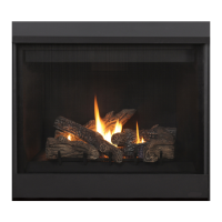
DRT40 Multi-View Series Direct-Vent Gas Fireplace
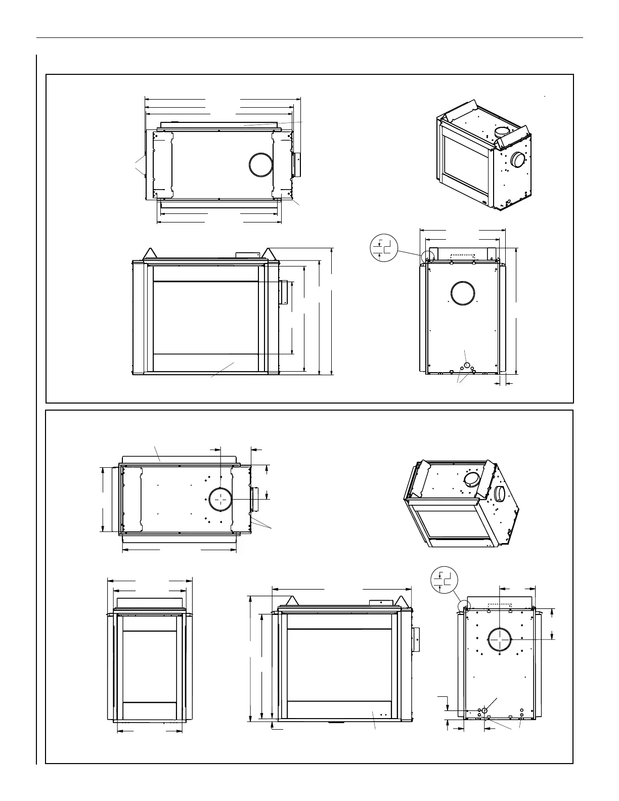
FIREPLACE SPECIFICATIONS
DRT40PF (Peninsula)
DRT40ST (See-Through)
Figure 18
Figure 17
NOTE: Unit has a factory-installed
vent seal cap and vent cover plate
(see Figures 22-23 on Page 17) in
each flue outlet. The vent seal cap is
not shown in this figure.
50-3/8 (1280)
48 (1219)
48-1/4 (1200)
37-3/4 (959)
40-1/4 (1023)
41
(1041)
37
(940)
34-1/8
(867)
23-1/2
(597)
27-3/4 (705)
23-7/8 (607)
41
(1041)
2 (51)
FRAMING
SPACERS
(Top and
both sides)
FINISHED WALL BRACKET
(Front and back edge of unit top)
Stepped to accept drywall
on all four corners
1/2
(13)
DETAIL OF
FINISHED
WALL BRACKET
GAS
INLET
CONTROL
COMPARTMENT
ACCESS PANEL
ST (See-Through)
TOP VIEW
FLUE SIDE VIEW
FRONT VIEW
ELECTRICAL
INLETS
10-3/8
(264)
12
(303)
3
(76)
6-7/8
(174)
41
(1041)
34-1/8
(867)
1 (26)
27-3/4 (705)
23-7/8 (607)
21-3/8 (543)
37-3/4 (959)
45-1/2 (1156)
11-3/8
(289)
10
(254)
21-3/8
(543)
TOP VIEW
FRAMING
SPACERS
(Top and
both sides)
(Front and back edge of unit top)
CONTROL
COMPARTMENT
ACCESS PANEL
ELECTRICAL
INLETS
GAS
iNLET
FRONT VIEW
LEFT SIDE VIEW
RIGHT SIDE VIEW
1/2
(13)
DETAIL OF
FINISH WALL BRACKET
NOTE: Unit has a factory-installed
vent seal cap and vent cover plate
(see Figures 22-23 on Page 17) in
each flue outlet. The vent seal cap is
not shown in this figure.