NOTE:DIAGRAMS&ILLUSTRATIONARENOTTOSCALE.
11
FRAMING SPECIFICATIONS
Figure 9
HoodKitInstallation(see ordering information on Page 16)
The firebox canopy (hood) must not be modified or replaced with a
canopy that may be provided with the unvented decorative room
heater.
NOTE: A hood comes standard and is required for model VTR2536WS.
The factory-supplied hood must be installed on the firebox for safe
operation for model VTR2536WS in all installations (this part is optional
for other models). See
Figure 13.
Thesehoodkitsaredesigntobettedtothefaceoftheappliancedirectly
abovethereboxopening.Inadditiontoprovidinganaestheticallypleasing
appearance to your appliance, the hood reduces heat effects to decora-
tivemantelsandnishmaterialslocateddirectlyabovethereplaceand
reducestheMantel/Trimclearances(seeFigures 4, 5 & 6 on Page 7).
Please read this entire manual and understood thoroughly before proceeding
with the installation of these kits.
Step 1.Usinga5/16"nutdriverorsocket,removethescreenandrod
assemblies as shown in Figure 12.
Step 2. Align the hood with the holes in the side frames as shown in
Figure 13. Install three screws as shown in Figure 13.Make
sure hood is level and secure.
Step 3. Reinstall screen and rod assemblies (see Figure 12).
Framing Dimensions
Opening VRT2536WS
VRT3536WS &
VRT3536WH
VRT3542WS &
VRT3542WH
A 42-1/4" (1073) 42-1/4" (1073) 48-1/4"(1226)
B 40-1/4" (1022) 44-1/4" (1124) 44-1/4" (1124)
C 23-9/16"(599) 23-9/16"(599) 29-9/16"(751)
D 11-1/4"(286) 11-1/4"(286) 14-1/4"(362)
E 63-1/2"(1613) 63-1/2"(1613) 69-1/2"(1765)
F 31-3/4" (807) 31-3/4" (807) 34-3/4" (883)
G 20-1/2"( 521) 20-1/2"( 521) 20-1/2"( 521)
H 44-3/16"(1122) 44-3/16"(1122) 49-1/8"(1248)
Table 1 -
This Table corresponds to Figures 9, 10 & 11
Rough Framing Face
(Unfinished Shown)
Back Wall Of Chase/Enclosure
Including Finishing Materials If Any
Rough Framing Face
(Unfinished Shown)
A
C
G
Parallel Installation
Figure 10
Figure 11
This Figure corre-
sponds to Table 1
This Figure corresponds
to Table 1
WARNING: Do not fill
spaces around the
firebox with insulation
or other materials.
A
B
Header
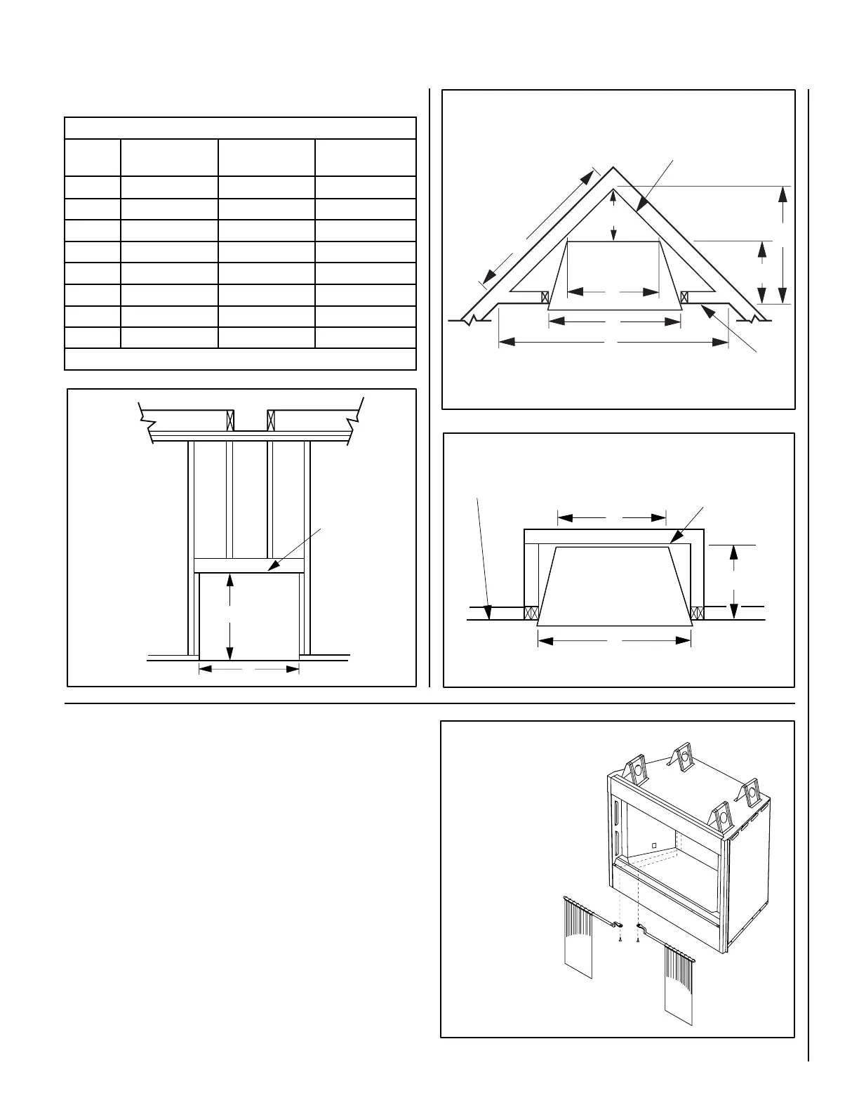
Figure 12
Removing Screens & Rods:
Remove screws (see dotted
lines). Pull out rods from
locatingholesonsideofrebox
opening.
Reinstalling Screens & Rods:
Insert rods into corresponding
locatingholesonsidesofrebox
opening, then reinstall screws
as shown.
A
C
D
H
F
G
E
Back Wall Of Chase/Enclosure
Including Finishing Materials If Any
Rough Framing Face
(Unfinished Shown)
Corner Installation
This Figure corresponds to Table 1