3-2 3-3
Chapter 3: System Interface
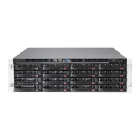
SUPERSTORAGESYSTEM 6038R-E1CR16H User's Manual
Power
Indicates power is being supplied to the system's power supply units. This LED
should normally be illuminated when the system is operating.
HDD
Indicates all hard drive activity (including DVD-ROM drives) when ashing.
NIC1
Indicates network activity on LAN1 when ashing.
NIC2
Indicates network activity on LAN2 when ashing.
3-3 Control Panel LEDs
The control panel located on the front of the SC836 chassis has ve LEDs. These
LEDs provide you with critical information related to different parts of the system.
This section explains what each LED indicates when illuminated and any correc-
tive action you may need to take.
Information LED
This LED will be blue when the UID function has been activated. When this LED
ashes red, it indicates a fan failure. When red continuously it indicates an overheat
condition, which may be caused by cables obstructing the airow in the system or
the ambient room temperature being too warm. Check the routing of the cables
and make sure all fans are present and operating normally. You should also check
to make sure that the chassis covers are installed. Finally, verify that the heatsinks
are installed properly (see Chapter 5). This LED will remain ashing or on as long
as the indicated condition exists.
Information LED States
State Indication
Fast Blinking Red (1x/sec) Fan Fail
Solid Red CPU Overheat
Slow Blinking Red (1x/4 sec) Power Fail
Solid Blue Local UID Button Depressed
Blinking Blue IPMI-Activated UID
Power Fail
Indicates a power supply module has failed. The second power supply module will
take the load and keep the system running but the failed module will need to be
replaced. Refer to Chapter 6 for details on replacing the power supply. This LED
should be off when the system is operating normally.
 Loading...