Chapter 6: Advanced Chassis Setup
6-36-2
SUPERSTORAGESYSTEM 6038R-E1CR16H User's Manual
6-4 System Fans
Three 8-cm hot-swap fans provide the cooling for the system. It is very important
that the chassis top cover is properly installed and making a good seal in order for
the cooling air to circulate properly through the chassis and cool the components.
System Fan Failure
Fan speed is controlled by system temperature via IPMI. If a fan fails, the remaining
fans will ramp up to full speed and the overheat/fan fail LED on the control panel will
turn on. Replace any failed fan at your earliest convenience with the same type and
model (the system can continue to run with a failed fan). Remove the top chassis
cover while the system is still running to determine which of the fans has failed.
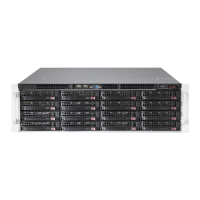
Figure 6-1. Front and Rear Chassis Views
6-2 Control Panel
The control panel on the front of the chassis connects to the JF1 connector on
the serverboard to provide you with system status indications. A ribbon cable has
bundled these wires together to simplify the connection. The LEDs inform you of
system status.
See Chapter 3 for details on the LEDs and the control panel buttons. Details on
JF1 can be found in Chapter 5.
6-3 Accessing the Inside of the Chassis
Some maintenance will require accessing the inside of the server.
Removing the Chassis Cover (Figure 6-2)
1. Remove the two screws from the sides of the chassis cover.
2. Press both release tabs at the same time to unlock the cover.
3. Slide the cover toward the rear of the chassis.
4. Lift the cover off the chassis.
Control Panel
SAS/SATA Drives (16)
Figure 6-2. Removing the Chassis Cover
Release Tab
Remove this screw
(if necessary)
1
1
1
1
1
2
Power Supplies
7 PCI Expansion Slots
I/O Ports2x Optional Hot-Swap 2.5"
Drive Bays
Hardware RAID Add-on Card
JBOD Expansion Ports
1
0
9
8
7
6
5
4
3
2
10
13
12
14
15
11
Note: numbers indicate the logical drive bay locations/.
 Loading...