1-2 1-3
Chapter 1: Introduction
SUPERSTORAGESYSTEM 6038R-E1CR16H User's Manual
1-2 Serverboard Features
The SuperStorageSystem 6038R-E1CR16H is built around the X10DRH-iT, a dual
processor serverboard based on the Intel C612 chipset. Below are the main features
of the X10DRH-iT. (See Figure 1-1 for a block diagram of the chipset.)
Processors
The X10DRH-iT supports single or dual Intel® Xeon E5-2600 (v3/v4) Series pro-
cessors. Please refer to the serverboard description pages on our website for a
complete listing of supported processors (www.supermicro.com).
Memory
The X10DRH-iT has 16 DIMM slots that can support up to 2 TB of Load Reduced
(LRDIMM) or 1 TB of Registered (RDIMM) ECC DDR4-2400/2133/1866/1600
memory. See Chapter 5 for details.
Main Storage Controller
An LSI 3108 controller card is included in the system to support up to 240 SATA
3.0/SAS 3.0 hard drives (RAID 0, 1, 5, 6, 10, 50 and 60 supported). The SATA/SAS
drives are hot-swappable units.
Serial ATA
A SATA controller is integrated into the chipset to provide 10 SATA 3.0 (6/Gbps)
ports (I-SATA0-5 supported by the Intel PCH and a vertical. 4-port S-SATA con-
nection supported by the Intel SCU), which are RAID 0, 1 and 10 supported. The
SATA drives are hot-swappable units. (RAID 5 supported with Windows OS only.)
PCI Expansion Slots
The X10DRH-iT has six PCI-Express 3.0 x8 slots (CPU1 Slots 1-3 and CPU2 Slots
5-7) and one PCI-Express 3.0 x16 slot (CPU2 Slot4). Note that slots 1 and 2 are
occupied by the controller and JBOD expansion port.
Rear I/O Ports
The I/O ports include one COM port, a VGA port, four USB (two USB 3.0 and two
USB 2.0), two 10G (TLAN) Ethernet ports, a dedicated IPMI LAN port and dual
JBOD expansion ports. A UID (Unit Identier) button and LED are also located
beside the VGA port.
Onboard Graphics
Graphics are provided by an onboard ASpeed AST 2400 BMC, which supports IPMI.
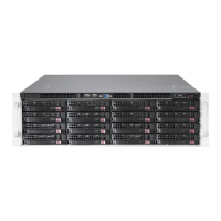
1-3 Server Chassis Features
The SC836BE1C-R920B is an ATX form factor chassis designed to be used in a
3U rackmount conguration. The following is a general outline of the main features
of the SC836BE1C-R920B server chassis.
System Power
The SC836BE1C-R920B features a redundant 920W power supply composed of
two separate power modules. This power redundancy feature allows you to replace
a failed power supply module without shutting down the system.
Hard Drive Subsystem
The SC836BE1C-R920B chassis was designed to support sixteen 3.5" hot-swap
SATA or SAS hard drives.
Front Control Panel
The control panel on the SC836BE1C-R920B provides you with system monitoring
and control. LEDs indicate system power, HDD activity, network activity, system
information and power supply failure. A main power button and a system reset but-
ton are also included. In addition, two USB ports have been incorporated into the
control panel to provide front side USB access.
Cooling System
The SC836BE1C-R920B chassis has an innovative cooling design that includes
three 8-cm hot-plug system cooling fans located in the middle section of the chas-
sis and two 8-cm rear exhaust fans. An air shroud channels the airow from the
system fans to efciently cool the processor area of the system. The power supply
modules also include a cooling fan.
 Loading...