35
Chapter 2: Installation
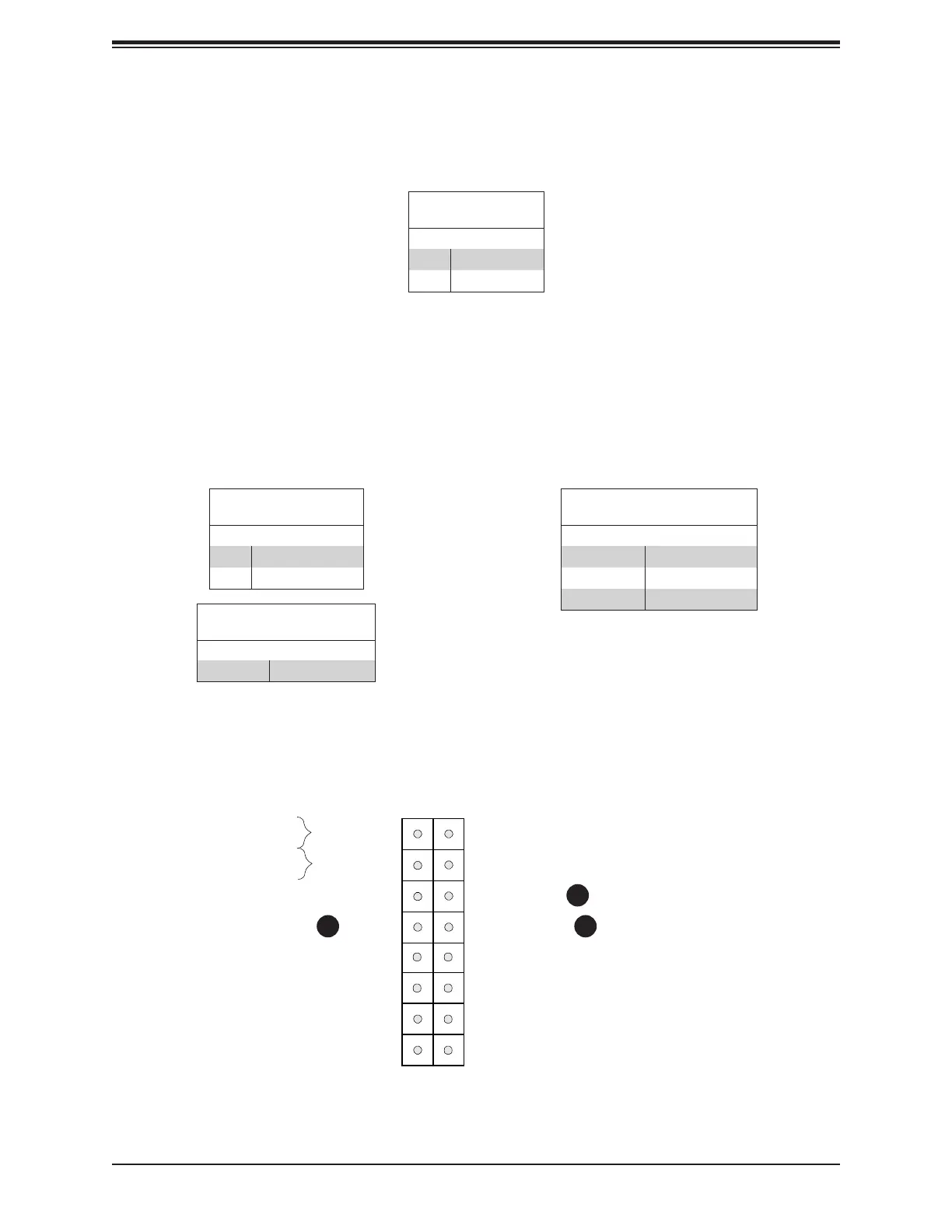
Power Fail
The Power Fail LED connection is located on pins 5 and 6. Refer to the table below for pin
denitions.
Power Button
UID LED
NIC1 Active LED
Reset Button
HDD LED
PWR LED
Reset
PWR
3.3V
3.3V Stby
3.3V Stby
Ground
15
3.3V Stby
3.3 V
OH/Fan Fail LED
16
1 2
Ground
Power Fail LED
NIC2 Active LED
1
2
PWR Fail
Pin Denitions (JF1)
Pins Denition
5 3.3V
6 Power Fail
OH/Fan Fail LED
Connect an LED cable to pins 7 and 8 of JF1 to use the Overheat/Fan Fail and UID LED
connections. The blue LED on pin 7 works as the front panel UID LED indicator. The red
LED on pin 8 provides warnings of overheating, fan failure or power failure. The red LED
takes precedence over the blue LED by default. Refer to the tables below for pin denitions.
UID LED
Pin Denitions (JF1)
Pins Denition
7 UID LED
8 OH/Fan Fail LED
1. Power Fail LED
2. OH/Fan Fail LED
3. UID LED
Power LED
Pin Denitions (JF1)
State Denition
Off Normal
On Overheat
Blinking Fan Fail
3
UID LED
Color and Status
Color Status
Blue: On Unit Identied

 Loading...


