2-2
AOC-CTGS-i2T Add-on Card User's Guide
2-3 Jumpers and Indicators
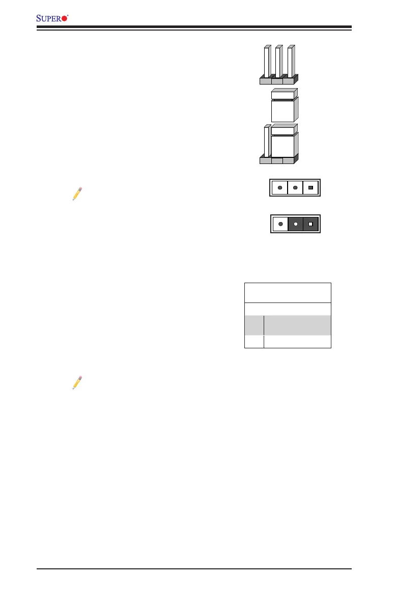
Explanation of Jumpers
To modify the operation of the add-on card, a
jumper can be used to choose between optional
settings. A jumper creates shorts between two
pins to change the function of the connector. Pin
1 is identied with a square solder pad on the
printed circuit board. See the add-on card layout
on page 2-1 for the jumper location.
Note: On two-pin jumpers, "Closed"
means the jumper is on and "Open"
means the jumper is o the pins.
Connector
Pins
Jumper
Cap
Setting
Pin 1-2 short
3 2 1
3.3V Standby PWR Enable
Jumper Settings
Pins Denition
1-2 Enabled
(See the note below)
2-3 Disabled (default)
3.3V Standby Power Enable
The 3.3V Standby Power Enable jumper is
located at JP1 on the add-on card. Refer to the
layout on page 2-1 for the location of the jumper.
Close pins 1 & 2 to enable 3.3V Standby Power
for Wake-on-LAN support. The default setting
is Disabled.
3 2 1
Note: If this jumper is set to "Enabled,"
LAN chip overheat may occur. Be sure
to provide adequate system cooling
when the jumper is enabled.
 Loading...