Do you have a question about the Supermicro AS -4125GS-TNRT and is the answer not in the manual?
Provides an outline of the server's functions and features.
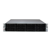
Offers an overview of the main features of the AS-4125GS-TNRT/TNRT1/TNRT2.
Details main component locations, block diagram, and motherboard layout.
Illustrates jumper, connector, and LED locations on the motherboard.
Provides advice and instructions for mounting the system in a server rack.
Details rackmount hardware and site preparation for installation.
Guides through installing the chassis into a rack unit using provided rails.
Outlines the procedure for safely removing power from the system.
Describes how to remove the top cover for internal access.
Covers installation of processors, heatsinks, memory, and other motherboard parts.
Details installation and removal of storage drives, fans, and power supplies.
Explains pin definitions for power supply and backplane connectors.
Details header pins for front panel buttons and LEDs.
Describes TPM and SATA connectors with their pin definitions.
Details pin definitions for fan, chassis intrusion, and IPMB headers.
Explains jumper functions, including CMOS clear.
Describes LAN port LEDs and onboard power status indicators.
Guides through installing the Operating System.
Provides instructions for downloading and installing system drivers.
Explains the SuperDoctor 5 utility for system monitoring.
Covers Baseboard Management Controller access and default password.
Details support for SATA, SAS, and NVMe drive configurations.
Lists available power supply module options and specifications.
Describes the cable management arm and its installation.
Explains the Trusted Platform Module (TPM) and its connection.
Lists website links for product specs, support, FAQs, and guides.
Describes the Baseboard Management Controller interface and its functions.
Provides general techniques and specific steps for common issues.
Lists beep codes and their corresponding error messages.
Explains how to download crash dumps for processor errors.
Guides on recovering the UEFI BIOS image and main BIOS block.
Details the procedure for clearing CMOS settings.
Explains how to reset the BMC using the UID button.
Advises on purchasing replacement parts from authorized sources.
Outlines procedures for contacting technical support.
Introduces industry standard warnings for bodily injury potential.
Explains the meaning of the general warning symbol.
Lists processor types and socket information.
Specifies the SoC chipset used.
Details the BIOS type and flash ROM size.
Provides memory capacity, slots, type, and speed.
Identifies the on-chip SATA controller.
Specifies the number and type of drive bays.
Lists the number and type of PCIe expansion slots.
Provides motherboard model and dimensions.
Details chassis model and rackmount dimensions.
Describes the type and number of system fans.
Lists power supply model, input/output specs, and certifications.
Details temperature and humidity ranges for operation.
Lists compliance standards like FCC, ICES, CE.
Lists EMC/EMI, Product Safety, and Environment directives.
| Memory Slots | 32 DIMM slots |
|---|---|
| CPU Socket | SP3 |
| Memory Capacity | Up to 4TB |
| SATA | 8 SATA3 ports |
| Storage Drive Bays | 12x 3.5" hot-swap drive bays |
| Networking | Dual 10GBase-T LAN |
| Management | IPMI 2.0 with KVM |
| Form Factor | 4U Rackmount |
| M.2 | 2x M.2 NVMe/SATA |