Do you have a question about the Supermicro AS -2024S-TR and is the answer not in the manual?
Provides a brief outline of the functions and features of the AS-2024S-TR server.
Instructions for inspecting and preparing the system for installation.
Overview of the main system specifications and capabilities.
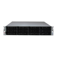
Details on the physical components and indicators of the server chassis.
Describes the buttons and LEDs on the server's front control panel.
Details the logical storage drive numbers and drive carrier indicators on the front.
Explains the LED indicators on the drive carriers for status and activity.
Identifies and describes the I/O ports and expansion slots on the rear of the chassis.
Explains the LED status indicators for the power supply modules.
Diagram and explanation of the motherboard's jumpers, connectors, and LEDs.
A summary table of jumpers, LEDs, and connectors for quick reference.
Introduces the chapter on mounting the system in a server rack.
Guidelines for choosing a location and preparing for server rack installation.
Recommendations for selecting a suitable environment for the server.
Safety guidelines for installing equipment in server racks.
General safety precautions for handling and installing the server.
Factors to consider for installing equipment into a rack assembly.
Considerations for preventing hazardous conditions due to uneven mechanical loading in racks.
Advice on power supply circuitry and potential circuit overloading.
Importance of maintaining a reliable ground connection for the rack and system.
Step-by-step instructions for installing the rack slide rails.
Explains how to identify the different sections of the rack rail assembly.
Procedure for releasing the inner rail from the outer rail assembly.
Steps for attaching the inner rails to the server chassis.
Guide for mounting the outer rails onto the server rack.
Instructions for sliding the server into the installed rack rails.
Procedure for safely removing the server chassis from the rack.
Essential steps to safely remove power from the system before maintenance.
How to remove the top cover to gain access to the system's interior.
Instructions for installing and replacing motherboard components.
Detailed guide for installing the CPU and its heatsink.
Covers memory support, population, installation, and removal.
Guide on installing PCI expansion cards.
Instructions for replacing the motherboard's CMOS battery.
Procedures for installing and replacing chassis components like storage drives.
Instructions for installing hot-swap drives and carriers.
Procedures for ejecting and replacing NVMe drives using IPMI.
Information on cooling, fans, air shroud, and airflow checks.
Troubleshooting steps for addressing system overheating issues.
Information on redundant power supplies, LEDs, and replacement.
Details on connecting the primary and auxiliary power to the motherboard.
Pin definitions for the 24-pin ATX main power connector.
Explains various headers and connectors on the motherboard.
Describes fan headers, DOM, SATA, M.2, SuperDOM, and Battery connectors.
Details TPM, Expansion Slots, UID, SGPIO, BMC, Chassis Intrusion, and Control Panel headers.
Explains pin definitions for control panel buttons and various system LEDs.
Describes the rear I/O ports available on the motherboard.
Identifies and describes COM, IPMI LAN, USB, LAN, and VGA ports.
Explains the function and settings of various motherboard jumpers.
Instructions for clearing the CMOS using the JBT1 jumper.
Describes Watch Dog, VGA, and LAN Enable/Disable jumpers.
Detailed explanations of the various onboard LED indicators.
Guide for installing the Windows operating system, including driver loading.
Instructions for downloading and installing system drivers from the Supermicro website.
Information on the SuperDoctor 5 utility for system health monitoring.
Details on the Baseboard Management Controller (BMC) and its administration.
Information on finding the default BMC administrator password.
Overview of the AMIBIOS Setup utility for the H12DSi-N6 motherboard.
How to access the BIOS setup utility by pressing keys during boot.
Describes the main BIOS setup screen and its configuration options.
Displays system date, time, BIOS version, build date, CPLD, and memory information.
Configuration options for advanced system settings in the BIOS.
Settings for boot features, trusted computing, firmware versions, and ACPI.
Settings for Super IO, Serial Port, SOL, console redirection, and CPU/NB.
Settings for xGMI, memory, PCIe, USB, network, and SATA interfaces.
Configuration for HTTP, iSCSI, and MBA boot protocols.
Settings for configuring the Intelligent Platform Management Interface (IPMI).
Options for managing system event logs, including enabling and erasing.
Settings for configuring the BMC's network interface and IP address.
Configuration options for SMBIOS event logging.
Options for enabling, disabling, and erasing SMBIOS event logs.
Configuration options for system security, including passwords and erase functions.
Settings for setting and checking administrator passwords.
Options for secure erase functions for storage devices.
Various security functions like password setting and erase modes.
Configuration options for system boot behavior and boot order.
Settings for boot mode (Legacy/UEFI/Dual) and boot device priorities.
Options for adding, deleting, and managing boot options.
Options for saving BIOS changes, discarding them, or resetting to defaults.
Options to save changes, discard changes, or reset to defaults and exit.
Explains the meaning of the standard warning symbols used in the manual.
Introduction to UEFI firmware and its role in system boot.
Explains the structure of the UEFI BIOS flash chip.
Step-by-step guide for recovering the BIOS using a USB device.
Lists the supported CPU types and socket information.
Identifies the chipset used in the system.
Specifies the BIOS type and capacity.
Details the number of DIMM slots and maximum memory capacity.
Information about the integrated SATA controller.
Specifies the number and type of drive bays supported.
Lists the types and number of PCI expansion slots available.
Provides the specifications and dimensions of the motherboard.
Provides the specifications and dimensions of the server chassis.
Details the cooling system, including the number and type of fans.
Specifications for the power supply units, including model and ratings.
Specifies the recommended operating and non-operating environmental conditions.
Lists the regulatory standards and directives the product complies with.
Specific warning regarding perchlorate materials in lithium coin cells.
| Brand | Supermicro |
|---|---|
| Model | AS -2024S-TR |
| Category | Server |
| Language | English |