59
Chapter 2: Installation
2.10 LED Indicators
LAN1 LEDs
The LED of LAN1 on the left indicates the speed of the connection, and the LED of LAN1 on
the right indicates activity. Refer to the tables below for more information.
LAN1 Link Indicator
LED Settings
LED Color Denition
O 10Mbps
Green 100Mbps
Amber 1 Gbps
LAN1 Activity Indicator
LED Settings
Color Status Denition
Yellow Flashing Active
LAN2 LEDs
The LED of LAN2 on the left indicates activity, and the LED of LAN2 on the right indicates
the speed of the connection. Refer to the tables below for more information.
LAN2 Activity Indicator
LED Settings
Color Status Denition
Yellow Flashing Active
LAN2 Link Indicator
LED Settings
LED Color Denition
O No Connection
Amber 5Gbps/2.5Gbps/
1Gbps/100Mbps
Green 10 Gbps
1. LAN1 LEDs
2. LAN2 LEDs
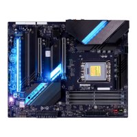
C9Z790-CGW
DESIGNED IN USA
REV:1.00
MAC CODEMAC CODE BAR CODE
BIOS
LICENSE
PCH
JLED_POGO2
JLED_POGO1
JRLED2
JRLED1
JTPM1
JLED_IO
SW1
JSTBY1
JD1
JSD1
JPW1
LED4801
LED18
LED17
LED1
LED3
LED2
JPW2
JL1
LED4
JPME2
JLED1
SYS_FAN1
SYS_FAN2
JWD1
22110
22110
2260
2280
PCH SLOT1 PCIe 3.0 X1
USB12 (3.2, 20Gb)
USB7 (3.2, 20Gb)
USB6 (3.2, 10Gb)
M.2-C1
12V_PUMP_PWR1
USB9 (3.2, 20Gb)
USB8 (3.2, 10Gb)
2280
SP1
B1
2260
2260
2280
BOOT LED
VGA LED
DIMM LED
CPU LED
DP/HDMI
LAN2
LAN1
JF1
AUDIO FP
COM1
USB4/5
USB10/11
(3.2, 5Gb)
M.2-P1
PCH SLOT5
PCIe
3.0 X1
CPU SLOT4
PCIe
5.0 X8 (IN X16)
CPU SLOT7
PCIe
5.0 X16
M.2-P2
SYS_FAN3
HD AUDIO
USB0/1/2/3
POWER
BUTTON
DIMMB1
DIMMB2
DIMMA1
DIMMA2
RESET
BUTTON
CPU_FAN1 CLEAR CMOS
CPU_FAN2
I-SATA4
I-SATA5
I-SATA2
I-SATA3
I-SATA0
I-SATA1
M.2-E1 (CNVi)
2 1
 Loading...
