11
Chapter 1: Introduction
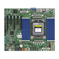
Quick Reference Table
Jumper Description Default Setting
UID SW Unit ID switch (push-button toggle switch ON/OFF) O
JBT1 CMOS Clear Open (Normal)
JSATA1 Hybrid MCIO select Pins 1-2 (Auto)
JPL1 LAN Enable/Disable Pins 1-2 (Enabled)
LED Description Status
UID_LED UID LED Solid blue: UID switched to ON, unit identied
LEDBMC BMC Heartbeat LED
Green: Blinking (BMC normal)
Green: Fast blinking (BMC initializing)
LED6 Power LED On: Power On
LED7 M.2-C2 Interface Detection On: SATA; O: PCIe
LED8 M.2-C1 Interface Detection On: SATA; O: PCIe
Connector Description
Battery (BT1) Onboard Battery
COM1 Rear panel COM port #1
FAN1, 2, 3, 4, A, B 4-pin System/CPU Cooling Fan Headers
JF1 Front Control Panel
JSD1, JSD2 SATA DOM power connector
JTPM1 Trusted Platform Module/Port 80 Connector
SATA0-7 SATA 0~7 via MCIO03
SATA8~11 Onboard SATA ports
SATA12-13; 14-15 SATA ports 12-13; 14-15
JL1 Chassis Intrusion Header
JOH1 Chassis overheat header
USB 0/1 (3.0) Back panel USB 3.0 ports (USB0/1)
USB 2/3 (3.0) Back panel USB 3.0 ports (USB2/3)
USB 4/5 (3.0) Internal USB 3.0 header (USB4/5)
JIPMB1 4-pin BMC External I
2
C Header (for an IPMI card)
JPWR1, JPWR2 12V 8-pin CPU core power supply connector
JPWR 3 24-pin ATX power supply connector
M.2-H1/M.2-H2 M.2 Slots
LAN1, LAN2 Back panel LAN1, LAN2 connectors
VGA Back panle VGA port
NVMe 0/1; 2/3; 4/5 NVMe slots 0~5
Note: Table continues on the next page.
 Loading...


