vii
List of Figures
Figure 3-1. Installing a Switch Module..............................................................3-2
Figure 3-2. Blade Enclosure with Switch Modules Installed..............................3-3
Figure 3-3. Configuring the Switch Module.......................................................3-4
Figure 3-4. Blade Status Screen.......................................................................3-5
Figure 3-5. Blade System Screen.....................................................................3-6
Figure 3-6. Switch Panel...................................................................................3-6
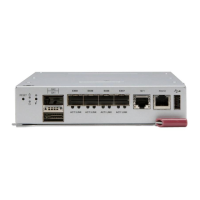
Figure 4-1. MBM-GEM-001 Gigabit Ethernet Switch Module ...........................4-1
Figure 4-2. MBM-GEM-004 Gigabit Ethernet Switch Module ...........................4-3
Figure 4-3. MBM-XEM-001 10-Gigabit Ethernet Switch Module.......................4-5
Figure 4-4. MBM-XEM-002 10-Gigabit Ethernet Switch Module.......................4-7
 Loading...