1-6
X9DR3-LN4F+/X9DRi-LN4F+ Motherboard User’s Manual
Warning: To prevent damage to the power supply or motherboard, please use a power
supply that contains a 24-pin and two 8-pin power connectors. Be sure to connect
these power supply connectors to the 24-pin power connector (JPW1) and two 8-pin
power connectors (JPW2, JPW3) on the motherboard. Failure in doing so will void the
manufacturer warranty on your power supply and motherboard.
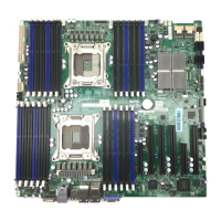
JTPM1 TPM (Trusted Platform Module)/Port 80
KB/Mouse PS2 Keyboard/Mouse
LAN1/3, LAN2/4 G-bit Ethernet Ports 1/3, 2/4
(IPMI) LAN IPMI_Dedicated LAN
SCU 0~3, 4~7 Storage Control Unit Connectors 0~3, 4~7 (X9DR3-LN4F+)
SP1 Onboard Buzzer (Internal Speaker)
USB 0/1 Back Panel USB 0/1
USB 2/3 Back Panel USB 2/3
USB 4/5, USB 6/7 Front Panel Accessible USB Connections 4/5, 6/7
USB 9 Front Panel Type A USB 9 Port
UID Switch UID (Unit Identier) Switch
VGA Backpanel VGA Port
X9DR3-LN4F+/X9DRi-LN4F+ LED Indicators
LED Description State Status
LE1 Standby PWR LED Green: On SB Power On
LE2 UID LED Blue Unit Identied
LEM1 BMC Heartbeat LED Green: Blinking Normal
 Loading...
