Chapter 1: Introduction
1-7
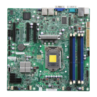
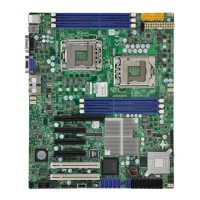
X9SCi-LN4/X9SCi-LN4F/X9SCA/X9SCA-F Headers/Connectors
Connector Description
B1 Onboard Battery
COM1, COM2 COM1 Backpanel Serial Port, COM2 Serial Port Header
BIOS SPI BIOS
Fans 1~4, Fan A System/CPU Fan Headers
JF1 Front Panel Control Header
JL1 Chassis Intrusion Header
JLED1 Power LED Indicator Header
JPW1 24-pin ATX Main Power Connector (Required)
JPW2 +12V 8-pin CPU power Connector (Required)
KB, Mouse Keyboard/Mouse Connectors
LAN1/LAN2/LAN3/LAN4 Gigabit (RJ45) Ports (LAN3/LAN4 is supported on the X9SCi-LN4 only)
IPMI LAN IPMI LAN (X9SCA-F/X8SCi-LN4F models only)
SATA 0/1 Serial ATA 3.0 Ports 0/1 (6Mb/s)
SATA 2~5 Serial ATA 2.0 Ports 2~5 (3Mb/s)
JPI
2
C PWR supply (I
2
C) System Management Bus
JSPK Speaker Header (Pins 3/4: Internal, 1~4:External)
JTPM Trusted Platform Module (TPM) Header
JWF1 SATA DOM (Disk On Module) Power Connector
JWOL Wake On LAN Header
SPKR1 Internal Speaker/Buzzer
T-SGPIO-1/2 Serial Link General Purpose I/O 1/2 Headers (5V Gen1/Gen 2)
USB0/1 Backpanel USB 0/1
USB2/3, USB4/5,
USB 12/13
Front Accessible USB Connections (via 3 Headers)
VGA Onboard Video Port
NIC LED3, NIC LED4 LED Headers for LAN3 and LAN4 (X9SCi-LN4 Only)
DIMM 1A, 2A, 1B, 2B 1066/1333 DDR3 DIMM Slots (ECC, Unbuffered type is required)
SW1 Unit ID Switch to turn on UID LED (LE5)
Slot 1~3 33MHz PCI Slots (Slot 2/3 are not available on the X9SCi series)
Slot 4~5 PCI-Express Slots x4 in x8 (Not available on the X9SCi series)
Slot 6 PCI-Express Slot x16

 Loading...
