33
Chapter 3 Motherboard Connections
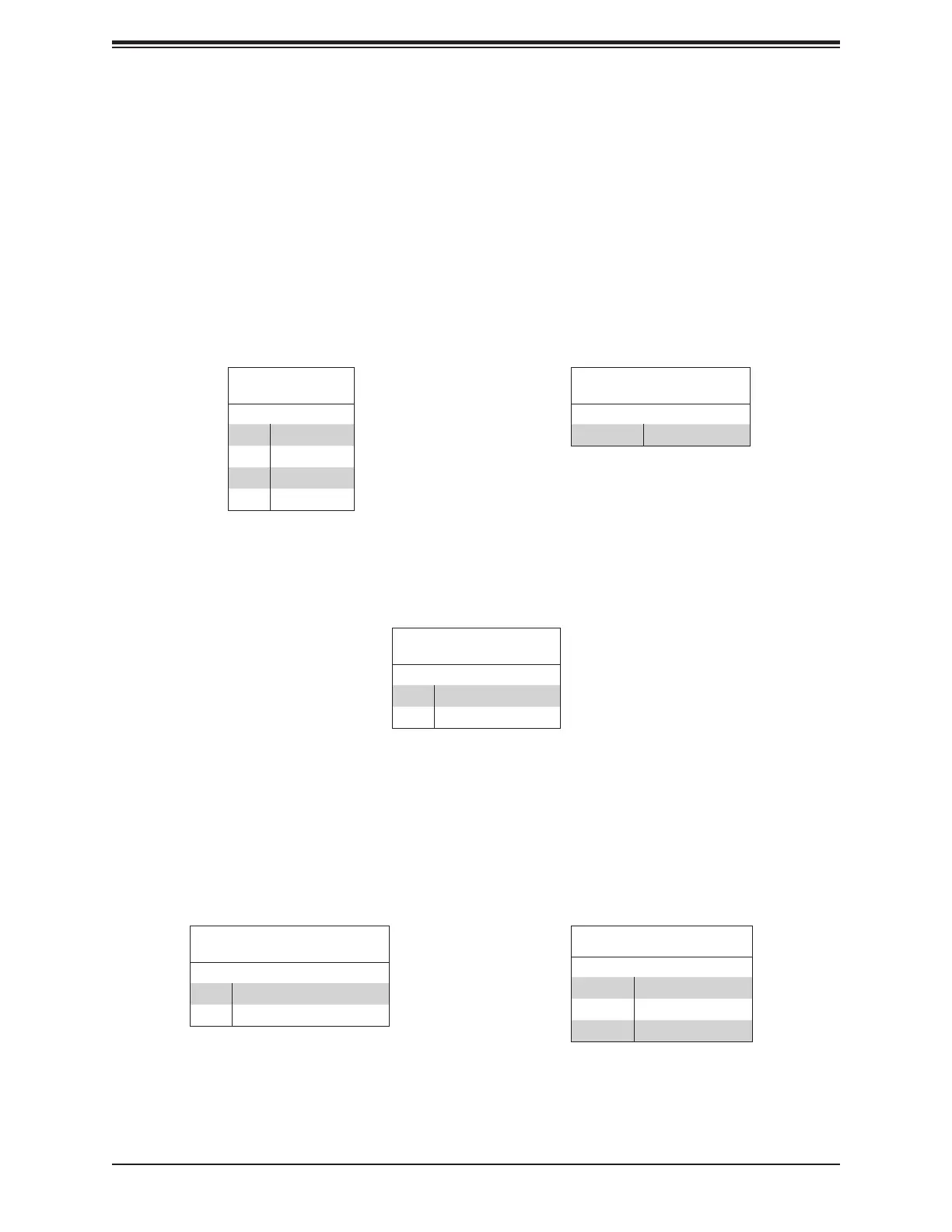
Unit Identier Switch/UID LED Indicator
switch is located at UID, which is next to the VGA port on the back panel. The UID LED
(LED2) is located next to the UID switch. When you press the UID switch, the UID LED will
Note: UID can also be triggered via IPMI on the motherboard. For more information
on IPMI, please refer to the IPMI User's Guide posted on our website at http://www.
supermicro.com.
UID Switch
Pin Denitions
Pin# Denition
1 Ground
2 Ground
3 Button In
4 Button In
UID LED
Pin Denitions
Color Status
Blue: On
Power Fail LED
The Power Fail LED connection is located on pins 5 and 6 of JF1.
Power Fail LED
Pin Denitions (JF1)
Pin# Denition
5 3.3V
6 PWR Supply Fail
Pin 8 Indicator Status
Status Denition
Normal
On Overheat
Flashing Fan fail
Overheat (OH)/Fan Fail
Connect an LED cable to pins 7 and 8 of JF1 (Front Control Panel) to use the Overheat/Fan
Fail and UID LED connections. The blue LED on pin 7 works as the front panel UID LED
indicator. The red LED on pin 8 provides warnings of overheating, fan failure or power failure.
The red LED takes precedence over the blue LED by default.
Overheat/Fan Fail and UID LED
Pin Denitions (JF1)
Pin# Denition
7 Blue LED
8 OH/Fan Fail