34
SuperServer E300-9A User's Manual
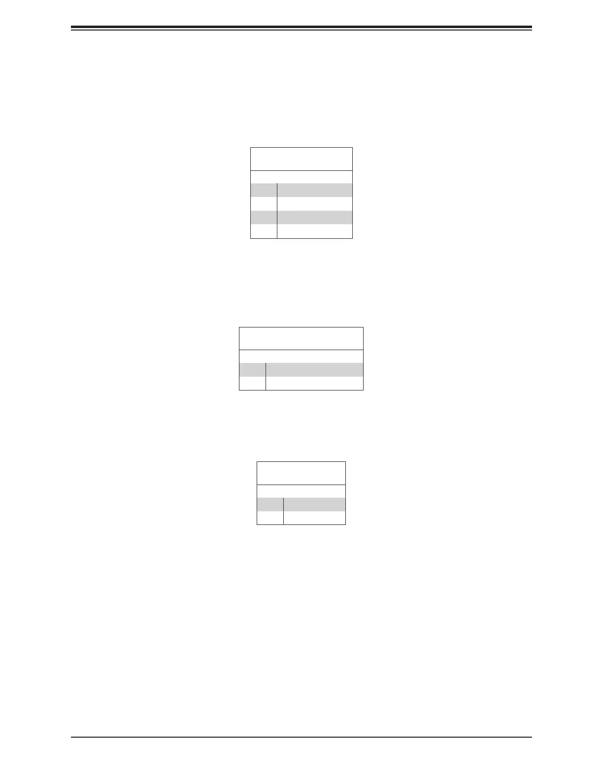
LAN1/LAN2 LED
Pin Denitions (JF1)
Pin# Denition
9 NIC2 Activity LED
10 NIC2 Link LED
11 NIC1 Activity LED
12
NIC1 Link LED
NIC1/NIC2 (LAN1/LAN2)
The NIC (Network Interface Controller) LED connection for LAN port 1 is located on pins 11
and 12 of JF1, and the LED connection for LAN Port 2 is on Pins 9 and 10. Attach the NIC
LED cables here to display network activity.
Power LED
The Power LED connection is located on pins 15 and 16 of JF1.
Power LED
Pin Denitions (JF1)
Pin# Denition
15 3.3V
16 Power LED
HDD LED/UID Switch
The HDD LED connection is located on pins 13 and 14 of JF1. Attach a cable here to indicate
the status of HDD-related activities, including SATA activities.
HDD LED
Pin Denitions (JF1)
Pin# Denition
13 3.3V Standby/UID Switch
14 HDD Active