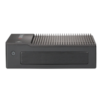
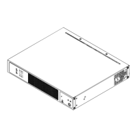
12
SuperServer E50-9AP-N5 User's Manual
Quick Reference Table
Jumper Description Jumper Setting
JLCDPWR1
Force Power On
Pins 2-4 (Force Power On)
Pins 4-6 (Power Button On)
LVDS Panel Power Source Selection
Pins 1-3 (3.3V)
Pins 3-5 (5V)
LED Description Status
LED1 Power LED
Solid Green: S0 mode
Solid Red: S3/S4/S5 modes
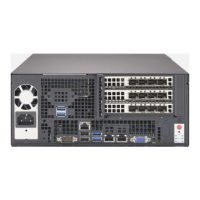
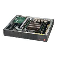
Connector Description
BT1 Battery Connector
I-SATA1 Intel PCH SATA 3.0 Port
J3 Front Panel Audio Header (Mic-In/Line-out)
J6 Two USB 2.0 Headers
JCOM1 Two COM Headers (two RS232/422/485)
JDC 12V DC Jack Power Connector
JEIO1
Supermicro Extension I/O
(HDMI/DP, two PCI-E x1, two USB 2.0, LPC, SATA, SMBus, Power)
JF1 Front Control Panel Header (Power/HDD LED, Reset, Power button)
JGP1 8-bit General Purpose I/O Header
JHDMI1
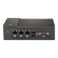
JLAN1/JLAN2 LAN1/LAN2 (RJ45 LAN) Ports
JMD1 M.2 Slot (B-KEY 2242/3042) (SATA 3.0 / PCI-E / USB 2.0)
JMP1 Mini PCI-E Slot (supports two PCI-E Gen2 / one USB 2.0)
JSMBUS1 SMBus and 5V/1A SATA Power Box Header
JUSB1 Two Rear Panel USB 3.0 Ports
LVDS1 Dual Channel 48-bit LVDS Connector
SRW1 - SRW2 M.2 and Mini PCI-E Mounting Holes