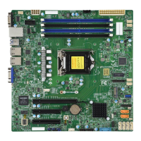
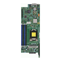
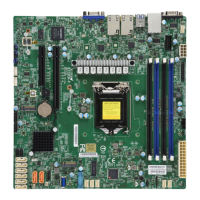
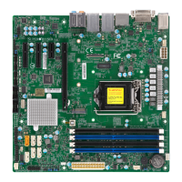
16
X11SCA/-W/-F User Manual
Quick Reference Table
Jumper Description Default Setting
JBT1 Clear CMOS Short: Clear CMOS,
Open: Normal
JPAC1 Audio Enable Pins 1-2 (Enabled)
JPG1 BMC GFX Chip Disable (X11SCA-F only) Pins 1-2 (Enabled)
JPL1 LAN1 Enable Pins 1-2 (Enabled)
JPL2 LAN2 Enable Pins 1-2 (Enabled)
JPME2 Manufacturing Mode Select Pins 1-2 (Normal)
JWD1 Watch Dog Enable Pins 1-2 (Reset)
LED Description Status
LED4 UID (X11SCA-F only) BLUE: Unit Identied
LED_PWR_SB Standby Power LED GREEN: P3V3 Standby Power Ready
BMC_HB_LED BMC Heartbeat LED GREEN Blinking: Normal
PWR_LED Onboard Power LED GREEN: Power On
Connector Description
AUDIO_FP Front Panel Audio Header
B3 Onboard Battery
COM1 COM1: Header
CPU SLOT4 PCI-E 3.0 x8
(INx16)
PCI Express x16 Slot (PCI-E 3.0 x8 link)
CPU SLOT6 PCI-E 3.0 x16 PCI Express x16 Slot (PCI-E 3.0 x16 link; x8 link when SLOT4 is used)
PCH SLOT7 PCI-E 3.0 x1 PCI Express x1 Slot
PCH SLOT2 PCI-E 3.0 x4 PCI Express x4 Slot (shared with M.2 #1)
PCI SLOT1 33MHZ PCIE Slot, 32 Bit/ 33MHZ with 5V single voltage
DP Back Panel DisplayPort
DVI Digital Video Interface
CPU_FAN1~2 CPU Fan Headers
SYS_FAN1~3 System Fan Headers
HD AUDIO Back Panel HD Audio Connectors
HDMI Back Panel HDMI port
I-SATA0 ~ I-SATA7 SATA 3.0 Connectors via Intel PCH (6Gb/s)
I-SGPIO 1/2 Serial Link General Purpose I/O Connection Headers for I-SATA 3.0
connections (I-SGPIO1 for I-SATA0~3, I-SGPIO2 for I-SATA4~5)
JF1 Front Control Panel Header
JL1 Chassis Intrusion Header
JLED1 3-pin Power LED Indicator Header
JPW1 24-pin ATX Main Power Connector (Required)
JPW2 +12V 8-pin CPU Power Connector (Required)
 Loading...
