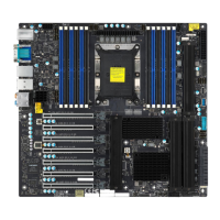
48
X11SCA/-W/-F User Manual
COM1
JBT1
B3
USB0/1 (2.0)
JPAC1
JPME2
JF1
JLED1
CPU SLOT6 PCI-E 3.0 X16
PCH SLOT2 PCI-E 3.0 X4
PCH SLOT7 PCI-E 3.0 X1
SLOT1 PCI 33MHZ
JWD1
JTBT1
CPU
PCI-E_M.2-M2
PCI-E_M.2-M1
I-SATA5
I-SATA3
I-SATA1
CMOS CLEAR
I-SATA4
I-SATA2
I-SATA0
I-SATA7
I-SATA6
U.2-1
USB4/5 (3.0)
USB8 (3.1,TypeC)
USB9 (3.1,TypeA)
SYS_FAN2
JPW1
SYS_FAN1
CPU_FAN1
JVR1
DIMMA1
DIMMA2
DIMMB1
DIMMB2
CPU_FAN2
SYS_FAN3
JPW2
JPL1
DVI
DP
HDMI
USB2/3(3.0)
USB6/7(3.1)
LAN1
LAN2
AUDIO
JPL2
I-SGPIO1
I-SGPIO2
JSTBY1
SPKR
SP1
JTPM1
AUDIO_FP
JPI2C1
CPU SLOT4 PCI-E 3.0 X8 (IN X16)
JL1
JSD1
LED_PWR_SB
1
1. Internal Buzzer
2. Thunderbolt Header
Internal Speaker/Buzzer
The Internal Speaker (SP1) can be used to provide audible notications using various beep
codes. Refer to the table below for pin denitions. See the layout below for the location of
the internal buzzer.
Internal Buzzer
Pin Definitions
Pin# Denition
1 Pos (+) DC 5V
2 Neg (-) Signal In
Thunderbolt Add-on Card Header
This motherboard supports one Thunderbolt header located at JTBT1. A Thunderbolt header
is a hardware interface that allows a Thunderbolt add-on card to be connected to the
motherboard.
Note: Support is limited to tested Thunderbolt cards that have 5-pin AIC cables. Please
contact your distributor or sales agent for details.
2
 Loading...
