55
Chapter 2: Installation
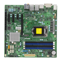
COM1
JBT1
B3
USB0/1 (2.0)
JPAC1
JPME2
JF1
JLED1
CPU SLOT6 PCI-E 3.0 X16
PCH SLOT2 PCI-E 3.0 X4
PCH SLOT7 PCI-E 3.0 X1
SLOT1 PCI 33MHZ
JWD1
JTBT1
CPU
PCI-E_M.2-M2
PCI-E_M.2-M1
I-SATA5
I-SATA3
I-SATA1
CMOS CLEAR
I-SATA4
I-SATA2
I-SATA0
I-SATA7
I-SATA6
U.2-1
USB4/5 (3.0)
USB8 (3.1,TypeC)
USB9 (3.1,TypeA)
SYS_FAN2
JPW1
SYS_FAN1
CPU_FAN1
JVR1
DIMMA1
DIMMA2
DIMMB1
DIMMB2
CPU_FAN2
SYS_FAN3
JPW2
JPL1
DVI
DP
HDMI
USB2/3(3.0)
USB6/7(3.1)
LAN1
LAN2
AUDIO
JPL2
I-SGPIO1
I-SGPIO2
JSTBY1
SPKR
SP1
JTPM1
AUDIO_FP
JPI2C1
CPU SLOT4 PCI-E 3.0 X8 (IN X16)
JL1
JSD1
LED_PWR_SB
1
CMOS Clear
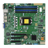
JBT1 is used to clear the CMOS. Instead of pins, this jumper consists of contact pads to
prevent accidental clearing of the CMOS. To clear the CMOS, use a metal object such as a
small screwdriver to touch both pads at the same time to short the connection.
Note: Be sure to completely shut down the system, and then short JBT1 to clear the
CMOS.
1. CMOS Clear
 Loading...
