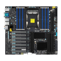
57
Chapter 2: Installation
COM1
JBT1
B3
USB0/1 (2.0)
JPAC1
JPME2
JF1
JLED1
CPU SLOT6 PCI-E 3.0 X16
PCH SLOT2 PCI-E 3.0 X4
PCH SLOT7 PCI-E 3.0 X1
SLOT1 PCI 33MHZ
JWD1
JTBT1
CPU
PCI-E_M.2-M2
PCI-E_M.2-M1
I-SATA5
I-SATA3
I-SATA1
CMOS CLEAR
I-SATA4
I-SATA2
I-SATA0
I-SATA7
I-SATA6
U.2-1
USB4/5 (3.0)
USB8 (3.1,TypeC)
USB9 (3.1,TypeA)
SYS_FAN2
JPW1
SYS_FAN1
CPU_FAN1
JVR1
DIMMA1
DIMMA2
DIMMB1
DIMMB2
CPU_FAN2
SYS_FAN3
JPW2
JPL1
DVI
DP
HDMI
USB2/3(3.0)
USB6/7(3.1)
LAN1
LAN2
AUDIO
JPL2
I-SGPIO1
I-SGPIO2
JSTBY1
SPKR
SP1
JTPM1
AUDIO_FP
JPI2C1
CPU SLOT4 PCI-E 3.0 X8 (IN X16)
JL1
JSD1
LED_PWR_SB
1. LAN1 Ports Enable/Disable
2. LAN2 Ports Enable/Disable
3. Manufacturing Mode
LAN Port Enable/Disable
Jumpers JPL1 and JPL2 enable or disable LAN ports 1 and 2 respectively on the motherboard.
Refer to the table below for jumper settings. The default setting is Enabled.
LAN1-LAN2 Enable/Disable
Jumper Settings
Jumper Setting Denition
Pins 1-2 Enabled
Pins 2-3 Disabled
1
2
Manufacturing Mode Select
Close pins 2 and 3 of jumper JPME2 to bypass SPI ash security and force the system to
operate in the manufacturing mode, which will allow the user to ash the system rmware
from a host server for system setting modications. See the table below for jumper settings.
The default setting is Normal.
Manufacturing Mode
Jumper Settings
Jumper Setting Denition
Pins 1-2 Normal
Pins 2-3
Manufacturing
Mode
3
 Loading...
