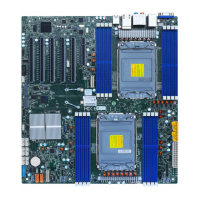
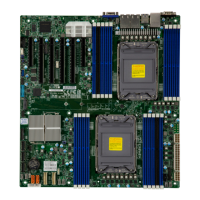
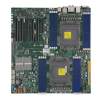
12
Super X12SPZ-SPLN6F/LN4F User's Manual
Note: Table is continued on the next page.
Quick Reference Table
Jumper Description Default Setting
JBM1 Disable IPMI Share LAN Pins 1-1 (Enabled)
JBM2 Disable IPMI Dedicated/Share LAN Pins 1-1 (Enabled)
JBT1 CMOS Clear Open (Normal)
JNS1 OCulink to 4x SATA or PCIe x4 Selection Pins 2-3 (PCIe x4)
JPDB1 COM1 Function Selection Pins 1-2 (BMC COM port)
JPG1 VGA Enable/Disable Pins 1-2 (Enabled)
JPL1 LAN5/6 Enable/Disable Pins 1-2 (Enabled)
JPL2 LAN1/2/3/4 Enable/Disable Pins 1-2 (Enabled)
JPME1 ME Recovery Mode Pins 1-2 (Normal)
JPME2 ME Manufacturing Mode Pins 1-2 (Normal)
JPT1 Onboard TPM Enable/Disable Pins 2-3 (Disabled)
LED Description Status
LEDBMC BMC Heartbeat Blinking Green: Device Working
LEDPWR Onboard Power LED Solid Green: Power On
UID LED Unit Identier LED Solid Blue: Unit Identied
Connector Description
BT1 Onboard Battery
COM1 COM Header
FAN1 - FAN4, FANA, FANB CPU/System Fan Headers (FAN1: CPU Fan)
IPMI LAN Dedicated IPMI LAN Port
J18 Extended CMOS Battery Connector
JD1 Speaker/Power LED Indicator (Pins 1-3: Power LED, Pins 4-7: Speaker)
JF1 Front Control Panel Header
JGP1 General Purpose I/O Header
JIPMB1 System Mangement Bus Header (for IPMI only)
JL1 Chassis Intrusion Header
JLANLED1 LAN3 - LAN6 Activity LED Header for SPLN6F
JLANLED1_1 LAN3 - LAN4 Activity LED Header for LN4F
JMD1 M.2 M-Key 2242/2280 (PCIe x4/SATA) Slot
JNVI
2
C1 Non-Volatile Memory (NVMe) I
2
C Header
JPH1 4-pin HDD Power Connector
JPI
2
C1 Power I
2
C System Management Bus (Power SMB) Header
JPW1 24-pin ATX Power Connector (Required)
JPV1 8-pin CPU Power Connector (Required)
 Loading...

