46
Super X12STL-F User's Manual
SATA Ports
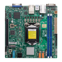
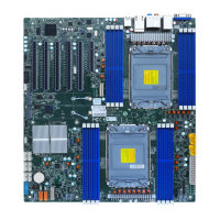
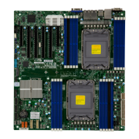
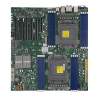
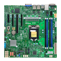
Six Serial ATA (SATA) 3.0 connectors (I-SATA0~5) are located on the motherboard. These
I-SATA 3.0 ports are supported by the Intel C252 PCH chip (supports RAID 0, 1, 5, and 10).
SATA ports provide serial-link signal connections, which are faster than legacy Parallel ATA.
Refer to the table below for pin denitions.
Note: For more information on the SATA HostRAID conguration, refer to the Intel
SATA HostRAID user's guide posted at https://www.supermicro.com/support/manuals/.
1. M.2 Slot
2. I-SATA0~5
M.2 Slot
This motherboard has one M.2 connector. M.2 was formerly known as Next Generation
Form Factor (NGFF) and serves to replace mini PCIe. M.2 allows for a variety of card sizes,
increased functionality, and spatial eciency. The M.2 slot on this motherboard supports PCIe
3.0 x4 in the 2280 and 22110 form factors.
BMC
JPG1
JWD1
I-SGPIO1
I-SGPIO2
M.2-P
M.2 NVME
I-SATA4
I-SATA3
I-SATA2
MEGERAC
LICENCE
BT1
CPU SLOT6 PCIe 4.0 x8 (IN x16)
PCH SLOT4 PCIe 3.0 x2 (IN x4)
CPU SLOT5 PCIe 4.0 x8
JBT1
REV:1.01
X12STL-F
JUIDB1
LED1
LEDM1
JPCIE7
FAN4
COM2
USB2/3
JIPMB1
JPME2
JPWR2
JPWR1
JPI2C1
JF1
USB6/7 (3.0)
JL1
JSD2
JSD1 USB8(3.0)
LED4
LED3
JSTBY1
FAN1FAN2
FAN3
FANAFANB
I-SATA1
I-SATA0
JPCIE6
JPCIE5
JPCIE4
JPCIE5
MH10
MH11
JTPM1
CPU SLOT7 PCIe 4.0 x4 (IN x8)
DIMMB1
DIMMA2
DIMMB2
DIMMA1
USB0/1
BMC_LAN
COM1
VGA
LAN2
LAN1
USB4/5
I-SATA5
CHASSIS INTRUSION
PWRI2C
DESIGNED IN USA
M.2
CPU
1
2
 Loading...
